Operation Manual IN2160 High Resolution VGA Video Interface
Installation and Safety Instructions For Models without a Power Switch: The socket outlet shall be installed near the equipment and shall be accessible. For Models with 110 / 220V Power Selector: Caution: Before applying power to this unit, the voltage selector must be set to the appropriate setting to match local A/C line voltage. Improper setting of the voltage selector may cause damage to the unit and create a potential fire hazard.
Installations und Sicherheitshinweise Für Geräte ohne Netzschalter: Die Netzsteckdose soll in de Nähe des Gerätes installiert und frei zugänglich sein. Für Geräte mit 110 / 220V Spannungswähler: Achtung: Bevor Sie dem Gerät Spann ung zuführen, muß der Spannungswähler entsprechend der Spannung des lokalen Wechselspannungsnetzes eingestellt werden. Die falsche Stellung des Spannungswählers kann eine Beschädigung des Gerätes und möglicherweise ein Feuer verursachen.
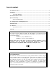
TABLE OF CONTENTS Description / Features ....................................................................................................................1 Installation ......................................................................................................................................2 Application Diagram...........................................................................................................2 Horizontal Position Control ................................................
1 DESCRIPTION The IN2160 is a high performance computer video interfaces dedicated for VGA, SVGA, and XGA, graphic cards. Like other Inline interfaces, the IN2160 performs the following functions: Signal Splitting - allows the simultaneous connection and viewing of both the computer’s local monitor and a second output device such as a large screen data projector, monitor, or color printer.
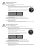
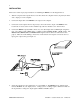
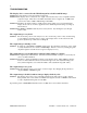
2 INSTALLATION This section offers step-by-step instructions for installing the IN2160. See the diagram below. 1. Turn the computer and computer monitor off. Disconnect the computer monitor (if present) from the video output port on the computer. 2. Connect the input cable of the IN2160 to the output of the computer. 3. Connect the local computer monitor (if present) to the local monitor output of the IN2160. If no local monitor is used, set the monitor emulation dip switch to emulate a color VGA monitor.
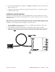
3 6. Connect the 9 VDC, 500 mA power adapter to the IN2160. The LED next to the power jack should light to indicate it is on. 7. Complete the installation by turning the computer and computer monitor on. If required, adjust the horizontal position control. HORIZONTAL POSITION CONTROL The location of the horizontal position control is diagrammed below.
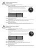
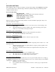
4 DIP SWITCH SETTINGS Most installations will not require any changes to the dip switch settings, and the IN2160 will generally be operated with the factory default settings. The Factory Default setting and specialized dip switch settings are indicated below.
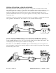
5 SPECIAL APPLICATION: LCD DISPLAY DEVICES When using an Interface with an LCD panel or projector, some special considerations must be made. Many LCD display devices utilize a “look-up table” when identifying an input signal. The display device compares the parameters of the input signal to those in its table and looks for a match. If there is no match to the signal format it is receiving, it may not be able to display the image properly.
6 TROUBLESHOOTING The display device connected to the IN2160 output has a bad/scrambled image. Solution 1: Verify that the correct input cable is being used. Solution 2: The display device connected to the output of the interface may not be compatible with the computer output. VGA runs at 31.5 KHz, but SVGA can be as high as 48 - 58 KHz with newer modes such as 1600 x 1200 running at 80+ KHz!.
7 SPECIFICATIONS Input Connector type RGB Video Signals Input Impedance Sync Signals Horizontal Scan Range Vertical Scan Range Output Connector Type Output Signal Formats RGB Signals Bandwidth Rise and Fall Times Gain Sync Signal Horizontal Pulse Width Vertical Pulse Width Controls External Internal Dimensions Size Shipping Weight Power Power Supply Regulatory Compliance Safety EMI 15 Pin HD male Analog, 0.7 Vp-p Nominal 75 Ohms TTL compatible 15.0 KHz - 135.
8 WARRANTY ♦ INLINE warrants the equipment it manufactures to be free from defects in materials and workmanship. ♦ If equipment fails because of such defects and INLINE is notified within two (2) years from the date of shipment, INLINE will, at its option, repair or replace the equipment at its plant, provided that the equipment has not been subjected to mechanical, electrical, or other abuse or modifications.