Operation Manual IN3554 4-Input RGBHV Switcher IN3556 6-Input RGBHV Switcher
Installation and Safety Instructions For Models without a Power Switch: The socket outlet shall be installed near the equipment and shall be accessible. For Models with 110 / 220V Power Selector: Caution: Before applying power to this unit, the voltage selector must be set to the appropriate setting to match local A/C line voltage. Improper setting of the voltage selector may cause damage to the unit and create a potential fire hazard.
Installations und Sicherheitshinweise Für Geräte ohne Netzschalter: Die Netzsteckdose soll in de Nähe des Gerätes installiert und frei zugänglich sein. Für Geräte mit 110 / 220V Spannungswähler: Achtung: Bevor Sie dem Gerät Spann ung zuführen, muß der Spannungswähler entsprechend der Spannung des lokalen Wechselspannungsnetzes eingestellt werden. Die falsche Stellung des Spannungswählers kann eine Beschädigung des Gerätes und möglicherweise ein Feuer verursachen.
CE COMPLIANCE All products exported to Europe by Inline, Inc. after January 1, 1997 have been tested and found to comply with EU Council Directive 89/336/EEC. These devices conform to the following standards: EN50081-1 (1991), EN55022 (1987) EN50082-1 (1992 and 1994), EN60950-92 Shielded interconnect cables must be employed with this equipment to ensure compliance with the pertinent Electromagnetic Interference (EMI) and Electromagnetic Compatibility (EMC) standards governing this device.
1 DESCRIPTION The IN3554 and IN3556 are high performance analog video switchers featuring four or six inputs and one output. The IN3500 Series switchers are designed to route several high resolution source signals to an attached video projector, monitor, LCD panel or color printer. Users may select the desired input channel using front panel buttons or via remote control using an optional wired remote or control system.
2 OPERATION Power Switch The POWER switch is located on the front panel and is a push, push again type switch which toggles between OFF and ON each time the button is pressed. The red power LED will light to indicate that the POWER switch has been activated and that an AC power source is available. The unit features AutoPower On, so once the POWER switch has been set to ON, the unit will be in that state if AC power is removed and then reapplied to the unit.
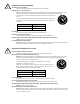
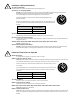
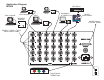
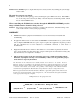
Application Diagram IN3556 DVD Player HORIZONTAL POSITION HORIZONTAL POSITION RED RED GREEN/ MONO INPUT BLUE BLUE H/COMP SYNC H/COMP SYNC POWER VIDEO GAIN V SYNC IN2005HR Interface IN1024 Scan Doubler ENTER MENU Scan Doubler ® IN1024 OUTPUT HORIZONTAL POSITION HORIZONTAL POSITION POWER Workstation w/ RGBHV Out RS-232 PORT MAC MAC 3 TM S-VIDEO VGA Computer 2005 UNIVERSAL ANALOG / DIGITAL HIGH RESOLUTION VIDEO INTERFACE V SYNC 2 VGA Computer VIDEO GAIN INPUTS TM COMPOSITE
4 Tally Output The REMOTE CONTROL port also provides tally outputs (pins 10 - 15) which may be used to trigger other devices, provide feedback to a control system, or light indicator lights on a custom remote control panel. When a channel is selected, either from the front panel or through the REMOTE CONTROL port, the Tally Output for that channel is switched on. The Tally Output can switch voltages of up to 50 volts and current up to 1.5 amps.
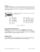
5 SPECIFICATIONS IN3554 / IN3556 RGBHV Switcher Inputs 5 BNC Female Connector type Number of Inputs IN3554: 4 Inputs IN3556: 6 Inputs Maximum Signal Components per Input Signal Compatibility 5 RGBHV, RGBS, RGsB, RsGsBs, Monochrome with Sync, Composite Video, Y/C, Component Video, Audio Output Connector type Bandwidth Isolation Switching Time Power 60 dB @ 50 MHz 5 BNC Female 500 MHz @ -3dB 55 dB @ 75 MHz 50 dB @ 100 MHz 3.
6 Solution 2: The RGBHV input or output cable may have a bad sync line. Try running the sync through another cable. The unit does not pass any signals. Solution: Verify that the unit is getting power by checking the power LED on the front. If the LED is not on, the AC power source may be faulty or the unit may have an internal problem. Check the two internal 200mA fuses. When controlling the IN3500 Series switcher through the REMOTE CONTROL port, the image is blanked and no channel is being selected.