
Owner's manual
1
© 1996-1997 - INLINE, INC. IN3554 / IN3556 OPERATION MANUAL - REV. 2.1 02/19/00
DESCRIPTION
The IN3554 and IN3556 are high performance analog video switchers featuring four or six inputs and
one output. The IN3500 Series switchers are designed to route several high resolution source signals to
an attached video projector, monitor, LCD panel or color printer. Users may select the desired input
channel using front panel buttons or via remote control using an optional wired remote or control system.
The IN3500 Series Switchers offer easy operation and the following features:
♦ 500 MHz Bandwidth - switchers route ultra-high resolution video signals with no signal loss
♦ Passive design ensures compatibility with a wide range of video and audio signals
♦ Front Panel Channel Selection Controls and LED Indicators
♦ Contact Closure control port for remote selection of input channel
♦ Front Panel Power Switch for easy operation in rack mounted installations
COMPATIBILITY
The IN3554 and IN3556 switchers are passive devices which will switch a wide variety of signals. These
switchers feature a set of five BNCs for each input and output connection and can switch five discrete
signal components for each input. While the units were primarily designed for use with high resolution
RGBHV analog computer graphics type signals, they may also be used to switch analog video signals in
any of the following formats: RGBS, RGsB, RsGsBs, Composite Video, S-Video (Y/C), Component
Video. Since the IN3554/3556 switch five discrete signal components simultaneously, they may also be
employed as audio-follow-video switchers. The IN3554 and IN3556 function very similarly and contain
the same control and switching circuitry. The main difference between the two models is the number of
inputs:
The IN3554 is a 4-Input, 1 Output RGBHV Switcher
The IN3556 is a 6-Input, 1 Output RGBHV Switcher
INSTALLATION
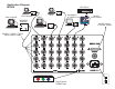
This section offers step-by-step instructions for installing IN3500 Series switchers. A detailed
application drawing showing all equipment connections is included on the next page.
1. Connect all sources to the IN3554/56 input connectors. Unused inputs do not need to be terminated.
2. An interface may be required for each computer video signal source in order to split off a signal for
each local monitor, bring all signals into the RGBS format, and amplify the signal to compensate for
long input/output cable runs.
3. Connect the IN3554/56 output to the display device.
4. Apply AC power to the unit.
It is very important that all input / output connections be made utilizing high resolution coaxial cables.
Proper cable selection is critical to overall system performance, especially when working with high
frequency signals and/or long cable runs. The IN7000-5, IN7100-5, or IN7200-5 Series 5 BNC Male to
5 BNC Male cables are recommended for best results.