
Owner's manual
2
IN3554 / IN3556 OPERATION MANUAL - REV. 2.1 02/19/00 ©1996-1997 - INLINE, INC.
OPERATION
Power Switch
The POWER switch is located on the front panel and is a push, push again type switch which toggles
between OFF and ON each time the button is pressed. The red power LED will light to indicate that the
POWER switch has been activated and that an AC power source is available. The unit features Auto-
Power On, so once the POWER switch has been set to ON, the unit will be in that state if AC power is
removed and then reapplied to the unit.
Input Selection
The IN3500 Series switchers provide four or six front panel buttons which may be used to select the
desired input channel. Any time the unit is powered up, Input 1 is automatically selected. In order to
select a different input, press the corresponding input button and the appropriate green LED will light to
indicate the current active channel. All non-selected channels are terminated to 75 Ohms. The output
signal may be blanked (no input selected) by pressing and holding any two input buttons simultaneously.
Input channels may also be selected remotely by using an optional IN3590 wired remote or a control
system (see Remote Control Operation on page 4 for more details).
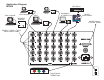
Since these switchers are passive they also bi-directional, meaning that signals may pass backwards
through the unit. In such an installation, a single source signal is hooked up to the OUTPUT connector
and multiple display devices are attached to the INPUT connectors. When an input is selected, the
source signal is routed to one of the attached display devices.
REMOTE CONTROL OPERATION
The IN3554/56 RGB switchers have a REMOTE CONTROL port which allows these units to be
remotely controlled. Channels can be selected through the remote port by providing contact closures
between the appropriate pins. The port also includes a +5V power supply and tally outputs. Several
contact closure type control devices are available including:
IN3590 - An optional hard wired remote designed to work with IN3500 Series switchers.
IN6901 / IN6902 RS232 to Contact Closure Converters - allow IN3500 Series switchers and
other INLINE devices with contact closure control ports to be controlled by RS232 sources such
as control systems and computer serial ports.
Control System - many control systems are capable of providing contact closures.
Control Parameters
In order to select a channel, the channel select pin (pins 1 - 6) must be connected to Common (pin 7 or 8).
The contact closures may be momentary or continuous (latching).
Example: To switch to Input Channel #4, apply a contact closure between Pin 4 and Pin 7.
If two channels are selected simultaneously, the output of the switcher is blanked (no output is selected).
In order to maintain blanking these two closures must be continuous.