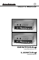
User's Manual xi SENTOSAxi LINE QUADRUPLER LANCIAxi xi LINE DOUBLER
Safety Instructions • English This symbol is intended to alert the user of important operating and maintenance (servicing) instructions in the literature provided with the equipment. This symbol is intended to alert the user of the presence of uninsulated "dangerous voltage" within the product's enclosure that may present a risk of electric shock. Caution: To prevent the risk of shock, do not remove the cover (or open the enclosure). There are no user-serviceable parts inside.
Extron's Warranty Extron Electronics warrants the product against defects in materials for a period of two years and defect in workmanship for a period of two years from the date of purchase.
Extron Electronics 1230 South Lewis Street Anaheim, CA 92805 (714) 491-1500 FAX (714) 491-1517 U.S.A.
Contents xi LQ & Lanciaxi xi LD ...................................... Chapter 1 Introduction to Sentosaxi Introduction .......................................................................................... 1-1 About this Manual ......................................................................... 1-1 Features ....................................................................................... 1-2 Specifications ...............................................................................
Legend of Icons The following icons may be used in this manual: ___ Important information – for example, an action or a step that must be done before proceeding. ___ A Warning – possible damage could occur. _ A Note, a Hint, or a Tip that may be helpful. __ Possible Electrostatic Discharge (ESD) damage could result from touching electronic components. __ Additional information may be referenced in another section, or in another document.
Extron’s SENTOSAxi & LANCIAxi User’s Manual 1 Chapter One xi & Lanciaxi xi Introduction to Sentosaxi Introduction Features Specifications Extron • SENTOSAxi LQ & LANCIAxi LD • User’s Manual
Introduction to the SENTOSAxi LQ & LANCIAxi LD Introduction About This Manual This manual contains operation/configuration information for the Sentosaxi Line Quadrupler (LQ) and Lanciaxi Line Doubler (LD). xi LD Facts and Features Sentosaxi xi LQ and Lanciaxi Extron’s Sentosaxi LQ and Lanciaxi LD are high resolution, digital video devices which convert interlaced video into non-interlaced video.
Introduction to the SENTOSAxi LQ & LANCIAxi LD • • • • • • • • • • • xi LD include the following. Features unique to the Lanciaxi Line doubler - Doubles the resolution of standard video from 525 interlaced lines at 15 kHz to 525 non-interlaced lines at 31.5 kHz for a clearer, brighter output. Demo-mode - Built-in “demo mode” allows split screen of video and line doubled video side by side. VGA mode - Conveniently converts video signals to 480 lines of non-interlaced VGA.
Introduction to the SENTOSAxi LQ & LANCIAxi LD xi LD Specifications Sentosaxi xi LQ & Lanciaxi Inputs Video level .. 0.7 – 1 volt p-p S-Video level (Y/C) .. Y = 0.7 volts p-p .. C = 0.3 volts p-p (burst) Connectors .. Video - female BNC .. S-Video - female 4-pin mini-DIN Impedance .. 75 ohms Outputs Video level .. 0.7 volts p-p Sync level .. 4-5 volts p-p (TTL) Sync polarity .. Composite – Negative .. H&V – Positive or Negative .. (DIP switch selectable) Sync output frequency .. Lanciaxi NTSC 3.58/4.
Extron’s SENTOSAxi LQ and LANCIAxi LD User’s Manual 2 Chapter Two Installation and Operation Rack Mounting Cabling Switch Settings DIP Switch Module Front and Rear Panels Operation Applications Extron • SENTOSAxi LQ & LANCIAxi LD • User’s Manual
Installation and Operation xi xi Installing the Sentosaxi xi/Lanciaxi If rack mounting is required it should be done before cabling, otherwise, skip to “Cabling” below. Rack Mounting The Sentosaxi/Lanciaxi can be rack mounted using one side of an optional 19” 1U Universal Rack Shelf (Extron PN# 60-190-01). To rack mount the Sentosaxi/Lanciaxi, do the following: 1. If feet were previously installed on the bottom of the case, remove them. 2.
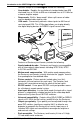
Installation and Operation 2. The BNC output connectors of the Sentosaxi/Lanciaxi should be connected to the display device using high resolution coaxial cable such as Extron’s BNC-4 or BNC-5. Connecting the RS-232 Cable To connect the Sentosaxi/Lanciaxi to a computer, refer to the picture below and connect the user supplied RS-232 cable from the Host system/device serial port to the Sentosaxi/Lanciaxi connector labeled RS-232. ___ When connecting to the RS-232 port, connect only pins 2, 3 and 5.
Installation and Operation Switch Settings The switches on the DIP switch module used in the Sentosaxi/Lanciaxi are the “rocker” type (see end view drawing, below-right). The primary difference between the rocker type and the “slide” type (which could also be used) is the action required to change the position of the switch. To change the position of the rocker type switch, press down against the desired end (enable or disable) with a pointed object.
Installation and Operation #2 – SERR REM (Serration Pulse Removal) Disabled – Serration pulses are passed along with the vertical sync pulse. Enabled – Serration pulses are removed from the output vertical sync pulse. #3 – SPLIT SCR (Sentosaxi = Tri-screen, Lanciaxi = split screen) Disabled – Split screen is disabled. Enabled – Split screen (Demo Mode) displays the selected input interlaced video on the left side of the screen. The remainder of the screen depends on the model.
Installation and Operation xi and Lanciaxi xi Front and Rear Panels (Sentosaxi xi) Front and rear panel component descriptions follow. Front Panel A B C D E F The letters next to the following descriptions match circled letters in the drawing below. Descriptions apply to Sentosaxi & Lanciaxi. Power LED – If the LED is on, power is on. If AC voltage is available to the device, power will be on. When power is initially applied, all front panel LEDs flash to indicate power up OK.
Installation and Operation Rear Panel M N O P Q R S T U V W The following descriptions are keyed* to the rear panel drawing below. Sentosaxi panel is pictured but also applies to Lanciaxi. AC Power connector Standard IEC AC power connector (100 - 240 VAC 50/60 Hz) 1 = Input connector #1 BNC connector for composite input video. 2 = Input connector #2 4 Pin mini-DIN connector for S-Video input. Switch Module 8 DIP switches described on pages 2-3 & 2-4.
Installation and Operation Operation xi Sentosaxi The Sentosaxi LQ converts interlaced video to non-interlaced video with four times the original number of horizontal scan lines. For NTSC 3.58/NTSC 4.43 video, each field of 262.5 lines is quadrupled to create a 1050 line non-interlaced screen scan. The same process applies to PAL/SECAM video, except the field consists of 312.5 horizontal lines which, when quadrupled, becomes 1250 horizontal lines/screen.
Installation and Operation Application with one input to the Sentosaxi or Lanciaxi provided by an SW 6 AV MX switcher. Application with one input to the Sentosaxi or Lanciaxi provided by a MAV 62 switcher. Application with one input to the Sentosaxi or Lanciaxi provided by a YCS SW6 MX switcher.
Installation and Operation Video Loop-Back Application Pictured below is an application using the Video Loop Back output from a System 8/10 PLUS Switcher as the input to a Sentosaxi LQ or a Lanciaxi LD. The output of the Sentosaxi/Lanciaxi is connected back to the last input (input 8 or 10) of the System 8/10 PLUS Switcher. This technique enables Line Doubling/Line Quadrupling for all inputs to the System 8/10 PLUS.
Extron’s SENTOSAxi LQ & LANCIAxi LD User’s Manual 3 Chapter Three RS-232/REMOTE Control RS-232 Control Windows Compatible Software Extron • SENTOSAxi LQ & LANCIAxi LD • User’s Manual
RS-232/REMOTE Control RS-232/REMOTE Control The Sentosaxi/Lanciaxi include an RS-232 communications interface which allows it to be controlled from a Host device/ system. RS-232 connector pin assignments and protocol are shown below. To Serial Port When RS-232 data is received by the Sentosaxi/Lanciaxi, the front panel MIN LED will blink once then the MAX LED will blink once to indicate that RS-232 data is being received. In EXEC mode the MIN and MAX LEDs are solid ON (see Page 2-5), they don’t blink.
= 1 – 127 = 0 or 1, 0 = OFF, 1 = ON = Software version x.xx = 1 – 63 Example Commands and Responses Response Action/Explanation Page 3-2 C2 Select Input channel #2 Frz1 Freeze (Frame) Video Frz0 Release Freeze Mode C2·T1·Col65·Tin70·Con100·Hph39·Frz0 C2·T1·Col65·Tin70·Con100·Hph39·Frz0 N60-213-01 60-213-01 = Lancia N60-229-01 60-229-01 = Sentosa QVER·1.23 (1.23 is example only) QVER·1.23 Software version 1.
RS-232/REMOTE Control Time-out Pauses 10 seconds or longer between command sequence ASCII characters will result in a Time-out. The command operation is aborted with no other indication that a Time-out has occurred. Error Responses • • • • When a command is received from the Host, if the Sentosaxi/ Lanciaxi detects an error, it will return an error response.
RS-232/REMOTE Control Lancia/Sentosa Control Software The Lancia/Sentosa Control Program is Windows® compatible and provides remote control of the following functions: • • • Input selection Video adjustments Freeze frame control Installing the Software The program is contained on a single 3.5” diskette and will run from the floppy drive. However, it will be more convenient to load and run it from the hard drive. It can be installed on the user’s hard-drive as follows: 1. 2.
RS-232/REMOTE Control Remote Contact Closure Operation The RS-232 connector provides a way to control the Sentosaxi/ Lanciaxi using a remote contact closure device. This is made possible through the use of pins that are not normally used by the RS-232 interface.
Extron’s SENTOSAxi LQ & LANCIAxi LD User’s Manual A Appendix A Other Reference Material Remote Contact Closure Operation Accessories and Part Numbers Limited Warranty Extron • SENTOSAxi LQ & LANCIAxi LD • User’s Manual
Other Reference Material Accessories/Part Numbers BNC-4 HR Cable BNC-4-3’HR (3 feet/0.9 meters) ........................................................... 26-210-01 BNC-4-6’HR (6 feet/1.8 meters) ........................................................... 26-210-02 BNC-4-12’HR (12 feet/3.6 meters) ....................................................... 26-210-03 BNC-4-25’HR (25 feet/7.5 meters) ....................................................... 26-210-04 BNC-4-50’HR (50 feet/15.0 meters) ............