User Guide Matrix Switchers CrossPoint 450 Plus Series CrossPoint Ultra Series MAV Plus Series Matrix Switchers 68-521-20 Rev.
Safety Instructions Safety Instructions • English WARNING: This symbol, , when used on the product, is intended to alert the user of the presence of uninsulated dangerous voltage within the product’s enclosure that may present a risk of electric shock. ATTENTION: This symbol, , when used on the product, is intended to alert the user of important operating and maintenance (servicing) instructions in the literature provided with the equipment.
FCC Class A Notice This equipment has been tested and found to comply with the limits for a Class A digital device, pursuant to part 15 of the FCC rules. The Class A limits provide reasonable protection against harmful interference when the equipment is operated in a commercial environment. This equipment generates, uses, and can radiate radio frequency energy and, if not installed and used in accordance with the instruction manual, may cause harmful interference to radio communications.
Conventions Used in this Guide Notifications The following notifications are used: WARNING: A warning indicates a situation that has the potential to result in death or severe injury. ATTENTION: Attention indicates a situation that may damage or destroy the product or associated equipment. NOTE: A note draws attention to important information. TIP: A tip provides a suggestion to make working with the application easier.
Contents Introduction............................................. 1 About this Guide.............................................. 1 About the Crosspoint and MAV Matrix Switchers.............................................. 1 CrossPoint Ultra Switchers............................ 5 CrossPoint 450 Plus Switchers....................... 6 MAV Plus Switchers...................................... 6 Definitions........................................................ 8 Features...................................
Programming Guide............................... 89 HTML Operation.................................... 131 Serial Ports...................................................... 90 Rear Panel RS-232/RS-422 Port................... 90 Front Panel Configuration Port.................... 90 Ethernet (LAN) Port......................................... 90 Default IP Addresses................................... 91 Establishing a Connection........................... 91 Connection Timeouts.............................
Introduction • About this Guide • About the CrossPoint and MAV Matrix Switchers • Definitions • Features About this Guide This guide contains installation, configuration, and operating information for the complete Extron family of full-function, medium- and large-sized, analog video matrix switchers, specifically: • CrossPoint 450 Plus large (matrix sizes from 24 inputs by 12 outputs to up to 32 inputs by 32 outputs) ultra-wideband RGBHV and audio matrix switchers • CrossPoint Ultra small (matrix
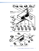
Class Room 101 Class Room 102 Class Room 106 Class Room 105 Class Room 104 Class Room 103 LAN Extron CrossPoint Ultra 128 HVA Ethernet Matrix Switcher 8 7 6 TP S UT 5 T SE RE LAN 1 ACT LINK OU 4 3 2 R G Extron DVS 304 O U T P U T LAN RESET R 6 OU B-Y VID TP UT 700 VSC RTER S CONVE SCAN X MIN/MA 2 5 E SIZE N/SIZ ER/PA CENT V 4 1 LINK 3 NC NEXT Extron VSC 700 MENU NC V SY 12 H SY E FREEZ RESET 11 2 IR 10 1 YC I N P U T 3 ACT V H/ HV Y,Y,B-Y RGB/R- .
MAV Plus series switchers offer multiple models of all matrix sizes, with one, two, or three (MAV Plus 1616 and smaller) video planes, to support different low resolution video formats (exceptions are noted in MAV Plus Switchers on page 6): • HDA for switching component/HDTV video and two-channel stereo audio • HD for switching component/HDTV video signals only • SVA for switching S-video and two-channel stereo audio • SV for switching S-video signals only • AV for switching composite video and two
The matrix switchers are housed in rack-mountable, metal enclosures with 19” rack ears.
Each model has an internal 100 VAC to 240 VAC, 50/60 Hz, switching power supply that provides worldwide power compatibility. The CrossPoint 450 Plus 2412, 2424, 3216, and 3232 and MAV Plus 2412, 2424, 3216, and 3232 each have two, primary and redundant, power supplies.
CrossPoint 450 Plus Switchers There are four CrossPoint 450 Plus series matrix sizes available, each in an HVA (RGBHV video and audio) and HV (RGBHV video only) model: • CrossPoint 450 Plus 2412 (24 inputs by 12 outputs) • CrossPoint 450 Plus 2424 (24 inputs by 24 outputs) • CrossPoint 450 Plus 3216 (32 inputs by 16 outputs) • CrossPoint 450 Plus 3232 (32 inputs by 32 outputs) The CrossPoint 450 Plus Series switchers have a minimum bandwidth of 450 MHz (-3 dB).
• • MAV 1616 Plus (16 inputs by 16 outputs) • HDA • HD • SVA • SV • AV • V • • • • A • A • A • A A MAV 2412 Plus (24 inputs by 12 outputs) • SVA • SV • AV • V MAV 2424 Plus (24 inputs by 24 outputs) • SVA • SV • AV • V MAV 328 Plus (32 inputs by 8 outputs) • • A MAV 248 Plus (24 inputs by 8 outputs) • • • A MAV 3216 Plus (32 inputs by 16 outputs) • SVA • SV • AV • V MAV 3232 Plus (32 inputs by 32 outputs) • SVA • SV • AV • V MAV Plus HDA and H
Definitions The following terms, which apply to Extron matrix switchers, are used throughout this guide: Tie — An input-to-output connection. Set of ties — An input tied to two or more outputs. (An output can never be tied to more than one input.) Configuration — One or more ties or one or more sets of ties. Current configuration — The configuration that is currently active in the switcher (also called configuration 0) Global memory preset — A configuration that has been stored.
Audio output volume (audio models) — The audio volume of each output can be displayed and adjusted through a range of full output to completely silent from the front panel or under serial port or Ethernet control. Digital Sync Validation Processing (DSVP) (CrossPoint) — In critical environments or unmanned, remote locations, it may be vital to know that sources are active and switching. The Extron DSVP confirms that input sources are active by scanning all sync inputs for active signals.
Switching flexibility — Provides individually buffered, independent matrix switched outputs with audio follow and audio breakaway for audio models. • Tie any input to any or all outputs • Quick multiple tie — Multiple inputs can be switched to multiple outputs simultaneously. This allows all displays (outputs) to change from source to source at the same time.
Three front panel security lockout modes (Executive modes) — If a matrix switcher is installed in an open area, where operation by unauthorized personnel may be a problem, either of two security lockout modes can be implemented (the third mode is unlocked). When a front panel locked mode is enabled, a special button combination or SIS command is required to unlock the front panel controller and make the front panel fully operational.
Installation This sections details the installation and configuration of the CrossPoint Matrix Switchers and MAV Plus Matrix Switchers, including: • Setup and Installation Checklist • Rear Panel Views • Rear Panel Connections • Front Panel Configuration Port Setup and Installation Checklist Get ready c Familiarize yourself with the matrix switcher. c Obtain IP setting information for the matrix switcher from the local network administrator (see Ethernet Connection on page 149).
Rear Panel Views All connectors for all switchers are on the rear panel. Figure 4 through figure 14, on the following pages, show a representative sampling of all of the matrix switchers described in this guide. See Rear Panel Connections, on page 19, for connecting cables to the rear panel connectors. ATTENTION: • Use electrostatic discharge (ESD) precautions (be electrically grounded) when making connections. Electrostatic discharge can damage equipment, even if you cannot feel, see, or hear it.
CrossPoint 450 Plus Switchers Figure 4 shows the CrossPoint 450 Plus 3232 HVA RGB video and stereo audio matrix switcher. NOTE: The CrossPoint 450 Plus 2412, 2424, and 3216 are housed in the same 10U or similar 8U enclosure, but have fewer output connectors to accommodate their smaller matrix sizes.
CrossPoint Ultra Switchers Figure 5 shows the CrossPoint Ultra 1616 HVA RGB video and stereo audio matrix switcher. NOTE: The CrossPoint Ultra 168 is housed in the same 6U enclosure, but has fewer input connectors to accommodate its smaller matrix size.
MAV Plus Switchers Figure 7 shows the MAV Plus 3232 SVA S-video and stereo audio switcher. NOTE: The MAV Plus 2412, 2424, and 3216 are housed in the same 8U enclosure, but have fewer input or output connectors to accommodate their smaller matrix sizes.
Figure 9 shows a MAV Plus 1616 HDA component/HDTV video and stereo audio switcher. NOTE: The rear panel of the MAV Plus 816 and 168 models have the same features as the MAV Plus 1616 series models (see figure 9 and figure 10), but have fewer input or output connectors to accommodate their smaller matrix sizes.
Figure 11 shows a MAV Plus 128 AV RCA composite video and stereo audio (with inputs and outputs on RCA connectors) matrix switcher. OUTPUTS INPUTS 1 2 3 5 4 7 6 9 8 10 12 11 1 3 2 5 4 7 6 8 LAN 12 ® US 2 4 3 5 6 8 7 9 10 11 12 1 2 3 4 5 6 7 L L L L L L L L L L L L L L L L L L L L R R R R R R R R R R R R R R R R R R R R LISTED 1T23 I.T.E. 6 Figure 11.
Figure 14 shows a MAV Plus 248 A audio matrix switcher (audio only). NOTE: The MAV Plus 328 is housed in the same 3U enclosure, but has more input connectors to accommodate its larger matrix size. LISTED 1T23 U SI.T.E.
CrossPoint 450 Plus 2412, 2424, 3216, 3232 Input 1 1 2 3 4 3 INPUTS INPUTS RED GREEN OUTPUTS 1 2 1 2 3 4 2 1 3 3 4 1 INPUTS OUTPUTS 4 1 2 3 2 3 4 1 INPUTS H HV SYNC BLUE OUTPUTS 4 2 1 1 2 3 3 4 INPUTS V SYNC OUTPUTS 4 2 OUTPUTS 4 1 2 3 4 Output 1 1 Input or Output 1 1 Input or Output 1 R 2 G 1 B 2 H 1 V 2 CrossPoint Ultra 84, 88, 124, 128 1 2 1 2 CrossPoint Ultra 816, 168, 1212, 1616 Figure 15.
Video (MAV Plus switchers) NOTES: • Video input and output connections are made with female BNC connectors. Some video input and output devices do not have BNC video output connectors. For these cases, a suitable cable or connector adapter is necessary. • The connectors for each video plane are grouped together (for example, for component/HDTV switchers, all of the Y inputs grouped together, all of the R-Y inputs grouped, and so on).
1 21 1 21 2 22 3 23 Y INPUTS 1 7 2 8 Y 2 3 4 1 22 23 O U T P U T S I N P U T S 24 24 4 21 C INPUTS 1 21 2 22 3 23 4 24 C 1 7 2 8 MAV Plus 816, 168, 1212, 1616 SVA and SV S-video 1 2 22 3 23 4 24 O U T P U T S I N P U T S MAV Plus 2412, 2424, 3216, 3232 SVA and SV S-video Figure 17.
Sync Termination Switches (CrossPoint) c Sync termination switches — The RGB (CrossPoint) matrix switchers have input Sync termination switches on the rear panel (see figure 19) that provide a way to condition non-TTL sync levels greater than 5V p-p. Sync termination enables the sync to be properly passed from input to selected output(s). The matrix switchers have two sets of sync termination switches; one for horizontal or combined sync and a second set for vertical sync.
Audio Input and Output (Audio Models) By default, the audio ties follow the video ties. Audio breakaway ties select from any one of the audio input sources and route it separately from its corresponding video source (see Example 3: Remove a tie from a set of ties on page 45). You can also use an SIS command (see page 95), the Matrix Switchers Control Program (see page 113), or the HTML pages (see Set and View Ties Page on page 142).
e Connections for balanced and unbalanced audio outputs — These 3.5 mm, 5-pole captive screw connectors output the selected unamplified, line level audio. Connect audio devices, such as an audio amplifier or powered speakers. See figure 22 to properly wire an output connector. Use the supplied tie-wrap to strap the audio cable to the extended tail of the connector. NO GROUND HERE Tip Ring L R Tip Ring R Do not tin the wires! L Tip Sleeves Tip NO GROUND HERE Unbalanced Stereo Output Figure 22.
RS-232/RS-422 Remote RS-232/RS-422 connector — Connect a host device, such as a computer, touch panel control, or RS-232 capable PDA to the switcher via this 9-pin D connector for serial RS-232/RS-422 control (see figure 23). 1 5 6 9 Figure 23.
Ethernet Ethernet port — If desired, for IP control of the system, connect the matrix switcher to a PC or to an Ethernet LAN, via this RJ-45 connector. You can use a PC to control the networked switcher with SIS commands from anywhere in the world. You can also control the switcher from a PC that is either running the Extron Windows-based control program or that has downloaded HTML pages from the switcher.
Reset button — The Reset button initiates various levels of reset to the matrix switcher. Press and hold the button while the switcher is running or while you power up the switcher for different reset levels. See Rear Panel Reset Operations on page 78, for details. LAN j RESET Reset Button NOTE: The CrossPoint 450 Plus and MAV Plus 2412, 2424, 3216, and 3232 do not have the Reset LED shown in the figure at right.
Figure 26 shows another configuration, in which the timing source passes through three video cameras and a video scan converter before connecting to the switcher. This type of video camera is capable of synchronizing with the external timing source for video editing applications.
Front Panel Configuration Port (All Matrix Sizes up to 1616, and MAV Plus 248A and MAV Plus 328A Only) 1 CONTROL ENTER PRESET VIEW I/O ESC VIDEO AUDIO CONFIG CROSSPOINT ULTRA SERIES ULTRA-WIDEBAND MATRIX SWITCHER WITH ADSP™ Figure 27. a Front Panel Configuration Port Configuration port — This 2.
Operation This section describes the front panel operation of the CrossPoint Matrix Switchers and MAV Plus Matrix Switchers, including: • Front Panel Controls and Indicators • Front Panel Operations • Rear Panel Operations • Optimizing the Audio (Audio Models) • Troubleshooting • Configuration Worksheets NOTE: The operation and appearance of all CrossPoint 450 Plus, CrossPoint Ultra, and MAV Plus switchers are very similar.
Comparison of Front Panels of Models Table 1. Switcher model 12 x 8 Panel 16 x 16 32 x 32 Figure CrossPoint Ultra 84, 88, 124, 128 MAV Plus 88, 128 29 CrossPoint Ultra MAV Plus 816, 1212, 1616 30 CrossPoint 450 Plus MAV Plus 248, 2412, 2424, 328, 3216, 3232 31 The pushbuttons can be labeled with text or graphics. The pushbuttons can be set to provide background illumination all the time or the background illumination can be turned off (see Background illumination on page 77).
3 4 5 1 2 3 4 5 6 7 8 9 10 11 12 13 14 15 16 1 17 18 19 20 21 22 23 24 25 26 27 28 29 30 31 32 I N P U T S 6 I/O C O NT R O L ENTER PRESET 1 2 3 4 5 6 7 8 9 10 11 12 13 14 15 16 2 17 18 19 20 21 22 23 24 25 26 27 28 29 30 31 32 O U T P U T S VIEW ESC RGBHV AUDIO 7 8 POWER SUPPLY PRIMARY REDUNDANT 9 CROSSPOINT 450 PLUS SERIES ULTRA-WIDEBAND MATRIX SWITCHER WITH ADSP ™ AND IP LINK ™ Figure 31. a b c d e Front Panel, CrossPoint 450 Plus 3232 Series Input buttons — See page 35.
Input and Output Buttons NOTES • Input and output buttons cannot select an input number or output number that is higher than your matrix size supports. Buttons numbered higher than your matrix size do have other functions as described in the following pages. : • See Front Panel Operations, beginning on page 40 for detailed descriptions of the following operations. Primary functions Action Select input or output for tie being created. Indication Blink: potential tie/untie.
a b Input buttons — The input buttons have one primary function (❏) and six secondary functions (•): ❏ Select and identify an input for ties or for audio level adjustment (audio models). • (Input 1) With the Output 1 button, select I/O Group mode. • Assign an input to the selected group in I/O Group mode and indicate its assignment. • Select a preset. • (CrossPoint switchers, Input 1 through 10) Display the RGB delay. • (Audio models) Display the volume of the selected output.
Control Buttons NOTE: See Front Panel Operations, beginning on page 40 for detailed descriptions of the following operations.
d e Preset button — The Preset button has two primary functions (❏) and three secondary functions (•): ❏ Activates Save Preset mode to save a configuration as a preset and Recall Preset mode to activate a previously-defined preset. ❏ Blinks when Save Preset mode is active and lights steadily when Recall Preset mode is active. • In the I/O Group mode, select group 2 and indicate the selection. • With the Enter, View, and Esc buttons, selects Serial Port Selection and Configuration mode.
I/O Controls NOTE: See Front Panel Operations, beginning on page 40 for detailed descriptions of the following operations. Primary functions Action Indication Select video Select audio Green: selected Red: selected RGBHV VIDEO AUDIO or Secondary functions Action 1 With Enter, select Lock mode 2 or toggle between mode 0 and mode 2. Action 2 Select Lock mode 1 or toggle between mode 2 and mode 1. RGB Delay Action/ indication Select RGB Delay mode. Blinks green.
h Audio button — The Audio button has one primary function (❏) and six secondary functions (•): ❏ Selects and deselects audio for a configuration that is being created or viewed and lights to indicate that audio is available for configuration or viewing. • (Audio models) Selects the Audio mode, in which you can adjust the analog input audio level and the analog output audio volume. • With the Enter button and RGBHV or Video button, selects between front panel locks (Lock mode 2 and Lock mode 0).
Front Panel Operations The following sections detail the power-up process and then provide sample procedures for the following actions: • Creating ties, sets of ties, and configurations • Changing a configuration • Viewing ties, sets of ties, and configurations • I/O grouping • Setting the RGB delay • Saving a preset • Recalling a preset • Muting and unmuting outputs • Viewing and Adjusting the Input Audio Level • Viewing and Adjusting the Output Volume • Locking and unlocking the front
Power Apply power by connecting the power cord between the switcher and an AC source. The switcher performs a self-test that flashes the front panel button indicators red, green, and amber and then turns them off. An error-free power-up self-test sequence leaves all input, output, and control buttons either unlit or showing background illumination.
Creating a Configuration The current configuration can be changed using the front panel buttons. Change the current configuration as follows: 1. Press the Esc button to clear any input button indicators, output button indicators, or control button indicators that may be lit. 2. Select video, audio, or both for configuration by pressing the RGBHV (CrossPoint switchers) or Video (MAV Plus switchers) button and Audio button as necessary. 3.
Example 1: Create a set of video and audio ties In the following example, input 5 is tied to outputs 3, 4, and 8. The steps show the front panel indications that result from your action. 1. Clear all selections: Press and release the Esc button. Press the Esc button to clear all selections. C O NT R O L ENTER PRESET VIEW ESC The button flashes once. 2.
The current configuration (see figure 33) is now input 5 video and audio are tied to output 3, output 4, and output 8 Figure 33. Final Configuration, Example 1 Example 2: Add a video tie to a set of video and audio ties In the following example, a new video tie is added to the current configuration. The example shows the front panel indications that result from your actions. NOTE: This example assumes that you have performed example 1. 1. Clear all selections: Press and release the Esc button. 2.
Press and release the Output 1 button. The button blinks green to indicate that only the selected RGBHV or video input will be tied to this output. C O NT R O L 1 2 3 4 5 6 7 8 15 16 17 18 19 20 21 22 23 24 31 32 O U T P U T S ENTER PRESET VIEW ESC The Enter button blinks green to indicate the need to confirm the change. 5. Confirm the change: Press and release the Enter button. Press the Enter button to confirm the configuration change.
Press and release the Input 5 button. The button lights red (matrix sizes up to 1616) or green (matrix sizes 2412 through 3232). 1 2 3 4 5 6 7 8 16 17 18 19 20 21 22 23 24 32 I N P U T S The Output 3, Output 4, and Output 8 buttons light red to indicate the audio ties created in example 1. 1 2 3 4 5 6 7 8 16 17 18 19 20 21 22 23 24 32 O U T P U T S The Output 1 button does not light to indicate the tie created in example 2 because that tie is RGBHV or video only. 4.
The current configuration (see figure 35) is now: • Video — Input 5 video is tied to output 1, output 3, output 4, and output 8. • Audio — Input 5 audio is tied to output 3 and output 8. Figure 35. Final Configuration, Example 3 Viewing the Configuration The current configuration can be viewed using the front panel buttons. The View-only mode prevents inadvertent changes to the current configuration.
4. Select the desired input or output whose ties you wish to view by pressing the input or output button. NOTES: • When you enter View-only mode, the output buttons light for all outputs without ties. Likewise, when you press an output button for which there are no ties, the output buttons light for all outputs without ties.
4. Select an input: Press and release the input 5 button. Press and release the Input 5 button. The button lights amber (matrix sizes up to 1616) or green (matrix sizes 2412 through 3232).
6. Toggle audio off and video on: Press and release the RGBHV (CrossPoint switchers) or Video (MAV Plus switchers) button and the Audio button. Press the RGBHV or Video button to select it. The button lights green when selected. Press the Audio button to deselect it. I/O VIDEO The button is unlit or background illuminated when deselected. AUDIO The output buttons for outputs that are tied to Input 5 light green to indicate RGBHV/Video ties (audio breakaway).
I/O Grouping I/O grouping is a matrix switcher feature that allows you to subdivide the front panel controls of the matrix into four smaller functional sub-switchers and limit tie creation using the front panel only. Tie creation via remote control is unaffected. Inputs and outputs can be assigned to one of four groups or not assigned to any group.
1. Press the Esc button to clear any input buttons, output buttons, or control buttons that may be lit. 2. To enter I/O Group mode, press and hold the Input 1 and Output 1 buttons simultaneously until the input and output buttons light to display the ungrouped inputs and outputs. Release the buttons. 3. Press and release one of the Control buttons to select a group: • Press the Enter button to select group 1. • Press the Preset button to select group 2. • Press the View button to select group 3.
Example 5: Grouping inputs and outputs In the following example, several switcher inputs and outputs are assigned to groups. The steps show the front panel indications that result from your action. 1. Clear all selections: Press and release the Esc button. 2. Enter I/O Group mode: Press and hold the Input 1 and Output 1 buttons for approximately 2 seconds and then release the buttons. Release the buttons. • Ungrouped input and output buttons light. 1 Press and hold the Input 1 button and Output 1 button.
5. Select group 2: Press and release the Preset button. Press and release the Preset button to select group 2. The button lights to indicate the selection. C O NT R O L ENTER PRESET Group # 1 2 VIEW ESC 3 4 6. Assign inputs and outputs to group 2: a. Press and release the Input 5 through 8 buttons. Press and release the Input 5 through Input 8 buttons. The selected buttons light. 1 2 3 4 5 6 7 8 15 16 17 18 19 20 21 22 23 24 25 32 I N P U T S b.
Setting RGB Delay (CrossPoint Switchers) The CrossPoint 450 Plus and CrossPoint Ultra switchers can briefly blank the RGB (video) output while it switches to the sync source of the new input, and then switches the RGB signals. This allows a brief delay for the display to adjust to the sync timing of the selected input before displaying the new picture, which will appear without glitches.
3. Select an output: Press and release the Output 17 button. The input buttons 1 through 10 display the RGB delay of the selected output. Each lit input button indicates half a second of delay. In this example, the lit input buttons display 3.5 seconds of RGB delay. 1 Press and release the Output 17 button. The button lights green. 2 5 16 17 18 11 32 O U T P U T S 0.5 1.0 1.5 2.0 2.5 3.0 3.
Using Presets The current configuration (configuration 0) can be saved as a preset in any one of 32 preset memory addresses. All 32 presets are assigned to the input buttons and (where necessary) output buttons and are available to be either saved or retrieved from the front panel. All 32 presets can be selected from the front panel to be either saved or retrieved. When a preset is retrieved from memory, it becomes the current configuration.
Example 7: Saving a preset In the following an example, the current configuration is saved as a preset. The example shows the front panel indications that result from your actions. 1. Clear all selections: Press and release the Esc button. 2. Select Save Preset mode: Press and hold the Preset button for approximately 2 seconds until it blinks. Preset Assigned Press and hold the Preset button until it blinks. PRESET 1 2 3 4 15 16 PRESET 2 seconds All input buttons with assigned presets light.
Example 8: Recalling a preset In the following example, a preset is recalled to become the current configuration. The steps show the front panel indications that result from your action. 1. Clear all selections: Press and release the Esc button. 2. Select Recall Preset mode: Press and release the Preset button. Preset Assigned Press and release the Preset button. The Preset button lights. 1 2 3 15 16 PRESET All input buttons with assigned presets light.
Muting and Unmuting Video and Audio Outputs Individual outputs can be muted or unmuted as follows: NOTE: Output mutes are protected when front panel Lock mode 2 is selected. You can view the status of the output (muted or unmuted) in Lock mode 2 but you cannot change it from the front panel (see Setting the Front Panel Locks (Executive Modes) on page 75). 1. Press the Esc button to clear any input button indications, output button indications, or control button indications that may be on. 2.
Example 9: Muting and unmuting an audio output In the following example, several switcher outputs are muted and unmuted. The steps show the front panel indications that result from your action. 1. Clear all selections: Press and release the Esc button. 2. Select View-only mode: Press and release the View button. The View button lights red. 3.
4. Mute outputs: One at a time: a. Press and hold the Output 3 button for approximately 2 seconds until the button begins to blink. b. Press and hold the Output 4 button for approximately 2 seconds until the button begins to blink. Mute outputs one at a time. 3 Press and hold the Output 3 button. NOTE: Video is muted in this example. 4 3 2 seconds The button blinks indicate that the output is muted. Green = Video is muted. Red = Audio is muted. Amber = Video and audio are muted.
Viewing and Adjusting the Input Audio Level (Audio Models) On models with audio, the level of each analog audio input can be displayed and adjusted through a range of -18 dB to +24 dB to ensure that there is no noticeable volume difference among sources (see figure 38). The audio level can be adjusted from the front panel or under remote control. The default audio level is 0 dB.
5. Press and release the Audio button to exit the Audio mode. The Audio button stops blinking. NOTES: • Pressing the Enter or Preset button also exits Audio mode. Pressing the Preset button changes to Recall Preset mode. • There is one level setting per analog audio input. The audio level setting is shared by the left and right audio inputs. • The audio level settings are stored in non-volatile memory. When power is removed and restored, the audio level settings are retained.
8-output Button and 16-output Button Audio Gain and Attenuation Display Table 3.
Example 10: Viewing and adjusting an input audio level Because of the different gain and attenuation display schemes, the input audio levels that result from the following example are shown two times: • As displayed on a 32-output button switcher • As displayed on a 16-output button switcher • As displayed on an 8-output button switcher The 32-button drawings show the actions that lead up to the display and the display itself.
Figure 41 shows the same level (+8 dB) as in figure 39, but displayed on an 8-output-button switcher, such as a MAV Plus 84 HDA. Flashing fast 2 3 4 5 1 6 7 8 OUTPUTS In this example, the output buttons display an audio gain level of +8 dB. Figure 41. Level Display on a 8-output-button Switcher 4. Change the audio level: Press and release the View (<) button once (see figure 42) to decrease the input audio level by 1 dB.
5. Exit Audio mode: Press and release the Audio button. Press the Audio button to exit audio mode. I/O The RGBHV or Video button lights green. RGBHV AUDIO The Audio button stops blinking and lights. All input buttons and output buttons return to unlit or background illumination.
Reading the displayed volume NOTE: This section is a detailed look at reading the output volume display on the front panel. If you do not need to read the exact value of the volume setting, skip this section. There are 65 steps of volume attenuation, with 1 dB per step (button push), except for 0-to-1, which is 13 dB. At maximum attenuation, no input buttons are lit, 76 dB of attenuation is applied, and the audio output is effectively muted.
Table 4.
Another way to view the volume level is to think in terms of the attenuation that is applied to the output. Attenuation reduction is indicated by the lit or blinking input buttons: when fewer input buttons are lit, attenuation is greater (and the volume is quieter). • At minimum volume, all input buttons are unlit or background illuminated and 76 dB of attenuation is applied to the output. The audio output is effectively muted.
Example 11: Viewing and adjusting a analog output volume level In the following example, the audio output volume is viewed and adjusted. The steps show the front panel indications that result from your action. Audio output volume is displayed differently on different models (see table 4 on page 70).
Figure 47 shows the same volume (41.5%) as in figure 45, but displayed on a 12-inputbutton switcher, such as a CrossPoint Ultra 128 HVA. Slow blinking button –39 dB attenuation, 41.5% volume INPUTS 1 2 3 4 5 6 7 8 9 10 11 12 • The input buttons display the selected output's audio volume level. • In this example, the lit or blinking input buttons indicate 40 to 41.5 percent of the applied audio input. • The unlit or blinking input buttons indicate an audio volume attenuation of 39 dB to 40 dB. Figure 47.
Figure 49 shows the same volume (61%) as in figure 48, but displayed on a 16-inputbutton switcher, such as a CrossPoint Ultra 168 HVA. Blinking Button -26 dB attenuation 61% volume INPUTS 1 2 3 4 5 6 7 8 9 10 11 12 13 14 15 16 • The input LEDs display the selected output’s audio volume level. • In this example, the lit/blinking input buttons indicate 59.5 to 62.5 percent of the applied audio input. • The unlit/blinking input buttons indicate an audio volume attenuation of 25 dB to 27 dB.
Setting the Front Panel Locks (Executive Modes) The matrix switchers have three levels of front panel security lock that limit the operation of the switcher from the front panel. The three levels are: • Lock mode 0 — The front panel is completely unlocked. All front panel functions are available. • Lock mode 1 — All changes are locked from the front panel (except for setting Lock mode 2). Some functions can be viewed. • Lock mode 2 — Basic functions are unlocked.
Selecting Lock mode 2 or toggling between mode 2 and mode 1 NOTE: If the switcher is in Lock mode 0 or mode 1, this procedure selects mode 2. If the switcher is in Lock mode 2, this procedure selects mode 1. Toggle the lock on and off by pressing and holding the RGBHV (CrossPoint Ultra) or Video (MAV Plus) button and the Audio button for approximately 2 seconds (see figure 52). Press and hold the buttons simultaneously to turn on Lock mode 2 or to toggle between mode 1 and mode 2.
Background Illumination The buttons on the front panel can be set to provide amber background illumination at all times or the background illumination can be turned off. To toggle the background illumination on or off, press and hold the Input 1 and Input 2 buttons simultaneously for approximately 2 seconds (see figure 54). Press and hold the buttons simultaneously to toggle background illumination mode on or off. 1 2 3 16 17 18 19 32 I N P U T S After approximately 2 seconds, release the buttons.
3. Change a value: Press and release the button that relates to the desired value. Press and release the button(s) to configure the port as follows: Baud rate: Enter — 9600 Preset — 19200 View — 38400 Esc — 115200 Serial protocol: RGBHV or Video — RS-232 Audio — RS-422/RS-485 The selected buttons blink and the others remain lit. In this example, the port is set to RS-422 at 38400 baud. I/O C O NT R O L ENTER PRESET VIEW ESC RGBHV AUDIO 4.
See table 5 for a summary of the modes. ATTENTION: Review the reset modes carefully. Using the wrong reset mode may result in unintended loss of flash memory programming, port reassignment, or a controller reboot. NOTE: The reset modes listed in table 5 close all open IP and Telnet connections and close all sockets. Also, the modes shown are separate functions, not a continuation from Mode 1 to Mode 5. Table 5.
Performing Soft System Resets (Resets 3, 4, and 5) — CrossPoint Ultra and MAV Plus 88, 128, 816, 164, 168, 1212, 1616, 248, and 328 Matrix Sizes Perform a soft reset of the switcher as follows: 1. Use a small screwdriver to press and hold the rear panel Reset button until the Reset LED and the front panel Video and Audio buttons blink the number of times for the desired reset: once (events reset), twice (system reset), or three times (absolute reset) (see figure 55).
Performing Soft Resets — CrossPoint 450 Plus and MAV Plus 2412, 2424, 3216, and 3232 Matrix Sizes The whole switcher reset function is identical to the front panel system reset (see Performing a System Reset from the Front Panel on page 81) without requiring you to power down the switcher. This function is also identical to theEZXXX} SIS command defined on page 104. System reset clears all ties and presets, resets all audio gains to unity gain (+0dB), and resets volume to 100% (0dB of attenuation).
Performing a Hard Reset — All Models The hard reset function (mode 1 for the sake of comparison with an Extron IPL product) restores the switcher to the factory default firmware. Event scripting will not start if the switcher is powered on in this mode. All user files and settings (drivers, adjustments, IP settings, and the like) are maintained. Perform a hard reset as follows: NOTES: • After a hard reset is performed, update the switcher firmware to the latest version.
Optimizing the Audio (Audio Models) The level for each analog audio input can be adjusted within a range of -18 dB to +24 dB, so there are no noticeable volume differences between sources and for the best headroom and signal-to-noise ratio. The volume for each analog audio output can be adjusted from full loudness to effectively muted. Adjust the levels as follows: 1.
Configuration Worksheets Rather than trying to remember the configuration for each preset, use worksheets to record this information. Make copies of the blank worksheet on page 87 (32-input button and -output button switchers)) and page 88 (16-input button and 12-input button switchers) and use one for each preset configuration. The worksheets accommodate all of the CrossPoint and MAV Plus models. Cross out all unused or inactive inputs and outputs. Use different colors for video and audio.
Worksheet Example 2: Daily Configuration Figure 59 continues from worksheet example 1 by showing the video and audio ties that make up the configuration of preset 1. Solid black lines shows video ties and red lines show the audio ties.
Worksheet Example 3: Test Configuration The A/V system in our fictional organization needs to be fine tuned on a regular basis. Figure 60 shows a typical test configuration, with an Extron video test generator (input 12) generating a test pattern to all monitors (outputs 1, 2, 3, 4, and 8, 9, 10, and 12). Sound checks are run from the CD player (input 5) to all audio systems (outputs 1, 2, 4, 5, and 8).
Input sources CrossPoint and MAV Series Matrix Switchers • Operation 1 2 3 4 5 6 7 8 9 10 11 12 13 14 15 16 17 18 19 20 21 22 23 24 25 26 27 28 29 30 31 32 1 2 3 4 5 6 7 8 9 10 11 12 13 14 15 16 17 18 19 20 21 22 23 24 25 26 27 28 29 30 31 32 Output destinations Preset # Title: Video: Audio: Fill in the preset number and use colors, or dashes, etc. to make connecting lines. Indicate if the configuration is for Video, Audio, or both.
Input sources 1 2 3 4 5 6 7 8 9 10 11 12 13 14 15 16 1 2 3 4 5 6 7 8 9 10 11 12 13 14 15 16 CrossPoint and MAV Series Matrix Switchers • Operation Output destinations Preset # Title: Video: Audio: Fill in the preset number and use colors, or dashes, etc. to make connecting lines. Indicate if the configuration is for video, audio, or both.
Programming Guide The CrossPoint and MAV Plus matrix switchers can be remotely controlled via: • The Matrix Switchers Control Program (see the Matrix Software, beginning on page 110) • Built-in HMTL pages (see HTML Operation, beginning on page 131) • SIS commands (see below) This section describes the operation of the CrossPoint and MAV Plus matrix switchers via SIS commands, including: • Serial Ports • Ethernet (LAN) Port • Host-to-Switcher Instructions • Switcher-Initiated Messages • Switch
Serial Ports The switchers have two serial ports that can be connected to a host device such as a computer running the HyperTerminal utility, an RS-232 capable PDA, or a control system. These ports make serial control of the switcher possible. The serial ports are: • The rear panel Remote (RS-232 or RS-422) port, a 9-pin D female connector • The front panel Configuration (RS-232) port, a 2.
Default IP addresses To access the CrossPoint or MAV Plus switcher via the LAN port, you need the IP address for the unit, and may need the subnet mask and the gateway address. If the IP address has been changed to an address comprised of words and characters, you can determine the actual numeric IP address using the ping (ICMP) utility (see Ethernet Link on page 149 for more details). If the addresses have not been changed, the factory-specified defaults are: • IP address 192.168.254.
Using Verbose Mode Telnet connections to an CrossPoint or MAV Plus switcher can be used to monitor for changes that occur on the switcher, such as front panel operations and SIS commands from other telnet sockets or a serial port. For a telnet session to receive change notices from the switcher, the telnet session must be in verbose mode 1 or 3. See the Verbose Mode SIS command on page 109. In verbose mode 3, the telnet socket reports changes in messages that resemble SIS command responses.
Sprnn] The switcher initiates the Spr message when a memory preset has been saved from the front panel. “nn” is the preset number. Rprnn] The switcher initiates the Rpr message when a memory preset has been recalled from the front panel. “nn” is the preset number. Innn•Audxx] The switcher initiates the Aud message when a front panel input audio level change has occurred. “n” is the input number and “xx” is the dB level.
Using the Command and Response Tables The command and response tables begin on the next page. Command and response examples are shown throughout the tables. With the exception of the audio input gain and attenuation commands, the SIS commands are not case sensitive. The ASCII to HEX conversion table below is for use with the command and response table.
X1@ X1# X1$ X1% X1^ X1& X1* X1( X2) X2! X2@ X2# X2$ = Video/audio mute: 0 = no mutes 1 = video mute 2 = audio mute 3 = video and audio mute = Sync frequency xxx.
Command and Response Table for SIS Commands (continued) Command Function SIS Command Response (Host to Unit) (Unit to Host) Additional description Read ties NOTE: The & read tie command for RGB and the % read tie command for video can be used interchangeably on the matrix switchers. X@& X@% X@$ X!] X!] X!] RGB input X! is tied to output X@. Video input X! is tied to output X@. Audio input X! is tied to output X@.
Command and Response Table for SIS Commands (continued) Command Function SIS Command Response (Host to Unit) (Unit to Host) Additional description Audio output volume NOTE: Table 11, below, the commands defines the value of each audio volume step. Set a specific audio volume Example: Increment volume Example: Decrement volume Read output volume X@*X*V OutX@•VolX*] 1*50v Out01•Vol50] X@+V OutX@•VolX*] 1+V Out01•Vol51] X@-V X@V OutX@•VolX*] X*] Table 6.
Command and Response Table for SIS Commands (continued) Command Function SIS Command Response (Host to Unit) (Unit to Host) X@*1Z X@*0Z X@Z AmtX@*1] X#] 1*Z Amt1] 0*Z Amt0] Additional description Audio mutes Mute audio Unmute audio View audio mute status Global audio mute Global audio unmute AmtX@*0] Mute output X@ audio (audio off). Unmute output X@ audio (audio on). Mute all audio outputs. Unmute all audio outputs.
Command and Response Table for SIS Commands (continued) Command Function SIS Command Response (Host to Unit) (Unit to Host) Additional description Direct write process — NOTE: The direct write of a global preset should always be preceded by a clear global preset ties command of that same preset number. In a directly-written preset, the input for each output position (or no tied input) remains unchanged unless overwritten or cleared.
Command and Response Table for SIS Commands (continued) Command Function SIS Command Response (Host to Unit) (Unit to Host) Additional description View ties, gain, volume, mutes, and presets (continued) View output mutes Example: CrossPoint 450 Plus 3232 HVA EVM} X1@1X1@2 ... X1@n] Each X1@ response is the mute status of an output, starting from output 1. n = the maximum number of outputs.
Command and Response Table for SIS Commands (continued) Command Function SIS Command Response (Host to Unit) (Unit to Host) Additional description View ties, gain, volume, mutes, and presets (continued) View video room preset configuration Command description: Response description: EX1)*X(*X@*1VC} X!n•X!n+1•...•X!n+15•Vid] Show room X1), preset X( video configuration. Show the input (X!) tied to 16 sequential outputs assigned to room X1), starting from output X@.
Command and Response Table for SIS Commands (continued) Command Function SIS Command Response (Host to Unit) (Unit to Host) Additional description I/O Grouping NOTE: The group that is assigned in each of the following I/O grouping commands (X1^) must be 1, 2, 3, 4, or 0 (not grouped). EX1^1X1^2...X1^nI} Write input grouping GriX1^1X1^2X1^3...X1^n] Each X1^ entry is the group number assigned to an input position, starting from input 1. n = the maximum number of inputs for this model.
Command and Response Table for SIS Commands (continued) Command Function SIS Command Response (Host to Unit) (Unit to Host) Additional description Names NOTE: The HTML language reserves certain characters for specific functions (see Special Characters on page 109). Write global preset name Example: Read global preset name Example: Write room preset name Example: Read room preset name EX(,X1!NG} E1,Security 1NG} EX(NG} E2NG} NmgX(,X1!] Nmg01,Security 1] Name global preset 1 “Security 1”.
Command and Response Table for SIS Commands (continued) SIS Command Response (Host to Unit) (Unit to Host) Reset global presets and names Reset one global preset Reset room map Reset individual room Reset all room presets and names Reset individual room preset and name Reset RGB delays Reset audio input levels EZG} EX(ZG} EZR} EX1)ZR} EZP} EX1)*X(ZP} Zpg] Clear all global presets and their names. ZpgX(] Clear global preset X(. Clear all room definitions.
Command and Response Table for SIS Commands (continued) Command Function SIS Command Response (Host to Unit) (Unit to Host) I VX1&XX1*•AX1&XX1*] Additional description Information requests Information request Example: MAV Plus 3216 HDA Request part number V (video) matrix size• A (audio) matrix size V32X16•A32X16] I X1(] N See the Extron website, www.extron.com, for part numbers.
Command and Response Table for SIS Commands (continued) Command Function SIS Command Response (Host to Unit) (Unit to Host) Additional description View and erase file directory NOTE: The response to the View File Directory command differs, depending on whether the command is sent via an RS-232, RS-422, or Telnet connection or sent via a Web browser connection. View file directory RS-232/RS-422 port and Telnet EDF} See below: List user-supplied files.
Command and Response Table for IP- and Remote Port Specific SIS Commands Symbol definitions X3) = Matrix name (Up to 24 alphanumeric characters) NOTE: The HTML language reserves certain characters for specific functions (see Special Characters on page 109). X3! X3@ = Default name Model name + last 3 pairs of MAC address. nn = 16 or 32.
X5# = Verbose mode 0 = clear/none (default for Telnet connection) 1 = verbose mode (default for RS-232/RS-422 connection) 2 = tagged responses for queries 3 = verbose mode and tagged for queries NOTE: If tagged responses is enabled (modes 2 and 3), all read commands return the constant string and the value as the set command does (for example, the read matrix name command ECN}, returns Ipn•X3!]).
Command and Response Table for IP- and Remote-Port-Specific SIS Commands (continued) Command Function SIS Command Response (Host to Unit) (Unit to Host) Additional description IP and Remote port setup commands (continued) EX4!,X4#,X4$,X4$,...,X4$EM} IpeX4%] Set e-mail events for recipient E72,3,1,2,8,32,98,99,EM} Example: CrossPoint 450 Plus 3232 Ipe•Jsmith@folklore.
Matrix Software This section introduces the following software programs, which are available on the Extron website (www.extron.com): • Matrix Switchers Control Program • Button-Label Generator Program Matrix Switchers Control Program The Windows®-based Extron Matrix Switchers Control Program provides an easy way to set up ties and sets of ties. The program is compatible with Windows 2000, Windows XP, and later. Updates to this program can be downloaded from the Extron website (www.extron.com).
Software Operation via a Serial Port • The serial ports are independent of one another. A front panel Configuration port connection and a rear panel Remote RS-232/RS-422 port connection can be active at the same time.
4. Enter the requested personal information; TIP: Click Remember Me to eliminate step 4 in future downloads. 5. Click Download to copy the software or firmware to your computer. 6. For a software download, click Run to confirm that you want to run the installation. 7. For a firmware download, exit this procedure and return to Updating Firmware on page 119 or Firmware Upgrade Page on page 140. 8. Follow the on-screen instructions.
Click OK and proceed to step 4. The Extron Matrix Switchers Control Program window (see figure 64 and figure 65 on the next page) appears, displaying the current configuration of the attached matrix. Proceed to step 4. • If you selected IP [LAN], click OK and proceed to step 3. • If you selected Emulate, click OK and see Using Emulation mode on page 127. 3. If you selected IP [LAN] in step 2, the IP Connection window appears (see figure 63). Figure 63. Address and Password Entry a.
Figure 64. Extron Matrix Switchers Control Program Window (no Icons or Ties) Figure 65.
IP Settings/Options window The IP Settings/Options window (click Tools > IP options, see figure 66) provides a location for viewing and, if connected via the either serial port or if you are logged on via the LAN port as an administrator, editing settings unique to the Ethernet interface. See the Ethernet Link section, beginning on page 149 for basic information about IP addresses. None of the fields on this screen can be edited while you are logged on as a user. Figure 66.
Valid addresses consist of four 1-, 2-, or 3-digit numeric subfields, properly called octets, separated by dots (periods). Each octet can be numbered from 000 through 255. Leading zeroes, up to 3 digits total per field, are optional. Values of 256 and above are invalid. The default addresses are as follows, but if these conflict with other equipment at your installation, you can change the addresses to any valid value: • IP address • Subnet mask 255.255.0.0 192.168.254.254 • Gateway address 0.0.0.
If desired, adjust any of these values as follows: 1. Click in the desired field. The field changes to an editable field appropriate to the value being change and the graphic cursor becomes a text cursor. • The Date field becomes a set date field, with the date in the format (M)M/(D)D/YYYY. Leading zeroes are not shown. • The Time (local) field becomes a set time field, with the time in the format HH:MM:SS (00:00:00 to 23:59:59).
Edit either password field as follows: 1. Click in the desired Password field. The pointer tool becomes a text cursor. 2. Edit the case-sensitive password as desired. 3. Press the key on the keyboard or click in another field to exit the Password field. 4. Click the Take button to make the password change take effect.
The radio buttons and check boxes associated with each address field permit the administrator to specify specific e-mail requirements for each recipient. Edit these fields and controls as follows: 1. Click in the desired E-mail Addressee field. The graphic cursor becomes a text cursor. 2. Edit the e-mail address as desired. Standard e-mail address conventions (for example: nnnnn@xxx.com) apply. 3. Press the key on the keyboard or click in another field to exit the e-mail addressee field. 4.
4 4 5 Folder where firmware is installed 6 Figure 68. Downloading Firmware Upgrade Files 5. Connect a Windows-based computer to either the Remote RS-232/RS-432 port (see item h on page 26), the front panel Configuration port (if equipped, see item a on page 30) or the LAN port (see item i on page 27) of the switcher. 6. If necessary, start the Matrix Switchers Control Program and connect to the matrix switcher (see Using the Matrix Switcher Control Software, steps 1 through 3, starting on page 112).
7. Click Tools > Update firmware... . • If the switcher is connected via the LAN port, the select file window appears (see figure 69 and “Ethernet-connected firmware upload,” below). 1 Figure 69. Select File Window • If the switcher is connected via either serial port, the Extron Firmware Loader window appears (see figure 70 and Serial-port-connected firmware upload on the next page). Ethernet-connected firmware upload 1. Navigate to the folder where you saved the firmware upgrade file.
Serial-port-connected firmware upload 1 Figure 70. Extron Firmware Loader Window 1. Select the matrix switcher and click File > New Firmware for Selected Devices. The Choose Firmware File dialog box opens (see figure 71). 2 2 Figure 71. Choose Firmware File Window 2. Navigate to and select the new firmware file. Click Open. The Choose Firmware File window closes. 3. In the Firmware Loader window, click Begin (see figure 72). The Total Progress and Progress status bars show the upload progress.
Uploading HTML Files You can create customized HTML pages for the switcher to display. The HTML Files List window (see figure 73) provides a way to view the contents of the switcher file system and to upload custom HTML pages to the switcher. Figure 73. HTML Files List Window Upload HTML pages as follows: NOTES: • The files listed in figure 73 are shown for example only and may not be present on your switcher. • The HTML Files List window is for inserting your custom HTML pages.
Windows Buttons, Drop Boxes, and Trash Can The buttons, drop boxes, and trash can on the right side of the Matrix Switchers Control Program window perform the following functions: Power — Unavailable for CrossPoint and MAV matrix switchers. Executive Mode — Allows you to lock out front panel operations, except for the view-only mode functions. Click the button to cycle between Lock mode 0 (the indicator is white), Lock mode 1 (the indicator displays red), and Lock mode 2 (orange).
Tools menu Assign device icons — Displays the complete set of input and output device icons. You can drag any of these icons to the input and output boxes. Edit device palette — Allows you to add your own custom device icon graphics. RGB delay settings — Displays the switching interval setting for each input and allows you to change them. Audio-Input gain settings — Displays the audio gain level setting for a single input or for all inputs and allows you to change it.
Name presets — Allows you to assign a name to each of the 32 memory presets. NOTES: • Preset names are limited to 12 upper- and lower-case alphanumeric characters. • Certain characters are reserved for specific functions (see Special Characters on page 109). Show RS-232 strings — Displays the RS-232 commands that are used by the current configuration. You can refer to these for SIS programming.
Frequency read options (CrossPoint only) — Allows you to set the input signal detection (DSVP) feature as follows: • To never sample and display the sync or no sync status (set this option to None) • To automatically refresh the display (set this option to Automatically every 10 seconds) • To sample the sync and update the display whenever you make a configuration change (set this option to On demand or by refresh).
3. Choose an emulation file to open, and click OK. The file DEMO.MTX provides a sample of a completed matrix setup. Selecting the file NEW.INI or clicking Cancel provides a blank setup window to get you started. 4. Enter the file name under which you want to save any changes to the file, and click OK. 5. See figure 78.
Button-Label Generator Program The Button Label Generator software creates labels that you can place in the translucent covers of the input and output selection buttons. You can create labels with names, alphanumeric characters, or even color bitmaps for easy and intuitive input and output selection (see the Removing and Installing Button Labels on page 158 for the procedure for removing and replacing the translucent covers).
Using the Button-Label Generator Software 1. To run the Button-Label Generator program, click Start > Programs > Extron Electronics > Button Label Generator > Button Label Generator. The Button-Label Generator window appears (see figure 80). Figure 80. Extron Button-Label Generator Window 2. In the Systems selection box, choose the Matrix Switchers 6464 option to match the button label size and quantities for your CrossPoint or MAV switcher. 3.
HTML Operation The CrossPoint or MAV Plus Matrix Switcher can be remotely controlled via: • SIS commands (see Programming Guide, beginning on page 89) • The Matrix Switchers Control Program (see Matrix Software, beginning on page 110).
Download the Startup Page Access the switcher using HTML pages as follows: 1. Start the Web browser program. 2. Click in the browser Address field. 3. Enter the Matrix IP address in the Address field of the browser. NOTE: If the local system administrators have not changed the value, the factoryspecified default, 192.168.254.254, is the correct value for this field. 4.
Status Tab System Status Page The System Status page (see figure 82) provides an overall view of the status of the matrix switcher, including individual voltages, fan operation, and the serial port status. The System Status page is the default page that the switcher downloads when you connect to the switcher. Access the System Status page from other pages by clicking the Status tab. Figure 82. System Status Page Components that are operating properly are indicated in green. Failures are indicated in red.
DSVP Page (CrossPoint Switchers) The DSVP page (see figure 83) displays a snapshot-in-time of the input frequencies of connected inputs. Access the DSVP page from the System Status or HDCP page by clicking the DSVP tab. The DSVP page automatically updates itself every 30 seconds to show the latest input frequencies changes or if an input has been disconnected. Figure 83.
On password-protected connections, there are two levels of protection: administrator and user. Administrators have full access to all switching capabilities and editing functions. Users can create ties, create and recall presets, set audio mutes, and view all settings with the exception of passwords.
MAC Address field The Media Access Control (MAC) Address is hardcoded in the switcher and cannot be changed. Firmware field The Firmware field identifies the installed firmware version. This field is hardcoded in the switcher and cannot be changed. Model and Part Number fields The Model and Part Number fields identify the switcher. These fields are hardcoded in the switcher and cannot be changed.
5. If appropriate, select the appropriate Daylight Savings radio button to turn on the daylight savings time feature for your region or nation. NOTE: When Daylight Savings Time is turned on, the switcher automatically updates its internal clock between Standard Time and Daylight Savings Time in the spring and fall on the date that the time change occurs in the country or region selected. When Daylight Savings Time is turned off, the switcher does not adjust its time reference. 6. Click the Submit button.
Email Settings Page Reach the Email Settings page (see figure 87) by clicking the Email Settings link on the left of the System Settings, Passwords, or Firmware Upgrade page. The Email Settings page has fields for setting up the e-mail notification capabilities of the switcher. For the e-mail settings and for each row of the e-mail notification settings, click the Edit button to make the fields available for editing. The button changes to Save.
3. Enter a user name and a password in the User Name and Password fields. For the CrossPoint or MAV Plus to accept their e-mail messages, senders must enter the user name and password. NOTES: • For the User name, any combination of letters, numerals, spaces, and symbols except the comma (,) and the single and double quotation marks (‘ and “) are valid. For the password, all characters except the comma are valid. The user name and password can each be from 1 to 30 characters.
Firmware Upgrade Page The Firmware Upgrade page (see figure 88) provides another way to replace the firmware that is coded on the control board of the switcher without taking the switcher out of service. Access the Firmware Upgrade page by clicking the Firmware Upgrade link on the left of the System Settings, Passwords, or Email Settings page. Figure 88.
5. Click the Firmware Upgrade link. 6. Click the Browse button. A Choose File to Upload dialog box appears. 7. Navigate to the folder where you saved the firmware upgrade file. Select the file. ATTENTION: The firmware file must have an .s19 extension. Other file types can cause the switcher to stop functioning. NOTES: • When downloaded from the Extron website, the firmware is placed in a subfolder of: • Windows 7 or Windows 8: C:\Program Files (x86)\Extron\Firmware.
To delete a file, click the Delete button associated with that file. Upload your own files as follows: NOTE: The HTML language reserves certain characters for specific functions (see Special Characters on page 109). 1. Click the Browse button. 2. Browse through your system and select the desired file of files. NOTE: If you want one of the pages that you create and upload to be the default startup page, name that file “index.html”. 3. Click the Upload File button.
The page displays the input and output buttons for inputs and outputs on installed boards only. Select and switch an input as follows: 1. Click the Video Only, Audio Only, or Video & Audio button to select video, audio, or both for switching (audio follow or audio breakaway). Each mouse click on a button toggles the other two buttons off. 2. Move the mouse over the matrix of input and output selection buttons.
Change the input gain and attenuation (audio models) Users can set the level of audio gain or attenuation of each input (-18 dB to +24 dB) from the RGB and Audio Settings page. Audio levels can be adjusted so there are no noticeable volume differences between sources. Change the audio level setting of an input as follows: 1. Click the Input drop box. A drop down scroll box appears (see figure 93). Figure 93. Input Selection Drop Box 2.
Mute and unmute one or all outputs Mute one or all outputs as follows: 1. To select an individual output to mute or unmute, click the Output drop box. A drop down scroll box appears (see figure 95). Figure 95. Output Selection Drop Box 2. Click and drag the slider or click the scroll up desired output is visible. button or scroll down button until the 3. Click the desired output. 4. Click the Video Only, Audio Only, or Video & Audio button to select video, audio, or both for muting.
4. Click the RGB delay Drop box. A drop down scroll box appears (see figure 97). Figure 97. RGB Delay Drop Box 5. Click the desired RGB delay. Change the output volume level (audio models) Change the volume level of an output as follows: 1. Click the Output drop box. A drop down scroll box appears (see figure 98). Figure 98. Output Selection Drop Box 2. Click and drag the slider or click the scroll up desired output is visible. button or scroll down button until the 3. Click the desired output. 4.
Table 7. dB of Number of steps attenuation Audio Volume Adjustment Settings Output volume Number of steps dB of attenuation Output volume Number of steps dB of attenuation Output volume 00 76 0% 01 63 5.5% 23 41 38.5% 45 19 71.5% 02 62 7% 24 40 40% 46 18 73% 03 61 8.5% 25 39 41.5% 47 17 74.5% 04 60 10% 26 38 43% 48 16 76% 05 59 11.5% 27 37 44.5% 49 15 77.5% 06 58 13% 28 36 46% 50 14 79% 07 57 14.5% 29 35 47.5% 51 13 80.
Global Presets Page You can save and recall global presets from the Global Presets page (see figure 100). Access the Global presets page by clicking the Global Presets link on the left of the Set and View Ties or RGB & Audio Settings page. Figure 100. Global Presets Page Saving a preset Save the current configuration (configuration 0) as a preset as follows: 1. Click the Save Preset button. 2. Select the desired preset by clicking on one of the presets listed.
Ethernet Connection This section provides a high level discussion of the Ethernet connection to the switcher and a primer on the subject of subnetting. Topics that are covered, include: • Ethernet Link • Subnetting — A Primer Ethernet Link The rear panel Ethernet connector on the CrossPoint or MAV Plus switcher can be connected to an Ethernet LAN or WAN. This connection makes SIS control of the switcher possible using a computer connected to the same LAN.
Pinging to Determine the Extron IP Address The ping utility is available at the Command prompt. Ping tests the Ethernet interface between the computer and the CrossPoint or MAV Plus switcher. Ping can also be used to determine the actual numeric IP address from an alias and to determine the web address. Ping the switcher as follows: 1. On the Windows task bar, click on Start > Run. 2. At the Open prompt, type command. 3. Click the OK button. 4.
Configuring the CrossPoint or MAV Plus Switcher for Network Use via the ARP Command The ARP (address resolution protocol) command tells your computer to associate the MAC (media access control) address of the CrossPoint or MAV Plus switcher with the assigned IP address. You must then use the ping utility to access the controller, at which point the IP address of the controller is reconfigured. Use ARP to configure the IP address as follows: 1.
6. After verifying that the IP address change was successful, enter and issue the arp –d command at the Command prompt. For example: arp –d 10.13.197.7 removes 10.13.197.7 from the ARP table or arp –d* removes all static IP addresses from the ARP table. Connecting as a Telnet Client The Microsoft Telnet utility is available from the Command prompt. Telnet allows you to input SIS commands to the CrossPoint or MAV Plus switcher from the PC via the Ethernet link and the LAN.
2. If necessary, at the password prompt, type the appropriate password and then press . Connection to the switcher via the Ethernet can be password protected. There are two levels of password protection: administrator and user. A person logged on as an administrator has full access to all matrix switcher switching capabilities and editing functions. Users can create ties, set mutes, and view all settings with the exception of passwords.
Quit Exit the Telnet utility by typing quit and then pressing at the Telnet prompt. If you are connected to the CrossPoint or MAV Plus switcher, access the Telnet prompt by typing the Escape character (+<]>). Subnetting — A Primer It is not the purpose of this guide to describe TCP/IP protocol in detail.
Subnet Masks and Octets The subnet mask (see figure 106) is used to determine whether the analog and remote devices are on the same subnet or different subnets. The subnet mask consists of four numeric octets separated by dots. Each octet can be numbered from 000 through 255. Leading zeroes, up to three digits total per octet, are optional. Each octet typically contains either 255 or 0.
Reference Information This section provides reference information for the CrossPoint or MAV Plus matrix switchers, including: • Mounting the Switcher • Removing and Installing Button Labels ATTENTION: Installation and service must be performed by authorized personnel only. Mounting the Switcher The matrix switchers are housed in rack-mountable, metal enclosures with 19” rack ears.
UL Guidelines The following Underwriters Laboratories (UL) guidelines pertain to the installation of the matrix switcher into a rack. • Elevated operating ambient temperature — If installed in a closed or multi-unit rack assembly, the operating ambient temperature of the rack environment may be greater than room ambient.
Removing and Installing Button Labels Making Labels from Paper Templates Figure 110 on page 159 provides strips of blank button labels. If desired, copy them or cut them out, write button information in each button area as desired, and put them in the windows of the input or output buttons. Installing Labels in the Buttons Install new labels in the front panel buttons as follows: 1.
Figure 110.
Extron Warranty Extron Electronics warrants this product against defects in materials and workmanship for a period of three years from the date of purchase.