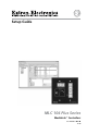
Setup Guide MLC 104 Plus Series MediaLink™ Controllers 68-1289-01 Rev.
Precautions Safety Instructions • English This symbol is intended to alert the user of important operating and maintenance (servicing) instructions in the literature provided with the equipment. This symbol is intended to alert the user of the presence of uninsulated dangerous voltage within the product’s enclosure that may present a risk of electric shock. Caution Read Instructions • Read and understand all safety and operating instructions before using the equipment.
安全须知 • 中文 警告 这个符号提示用户该设备用户手册中 有重要的操作和维护说明。 电源 • 该 设 备 只 能 使 用 产 品 上 标 明 的 电 源 。 设 备 必须使用有地线的供电系统供电。 第三条线 (地线)是安全设施,不能不用或跳过。 这个符号警告用户该设备机壳内有暴 拔掉电源 • 为安全地从设备拔掉电源,请拔掉所有设备后 或桌面电源的电源线,或任何接到市电系统的电源线。 露的危险电压,有触电危险。 电源线保护 • 妥善布线, 避免被踩踏,或重物挤压。 注意 阅读说明书 • 用 户 使 用 该 设 备 前 必 须 阅 读 并 理 解所有安全和使用说明。 保存说明书 • 用户应保存安全说明书以备将来使 用。 遵守警告 • 用户应遵守产品和用户指南上的所有安 全和操作说明。 维护 • 所有维修必须由认证的维修人员进行。 设备内部没 有用户可以更换的零件。为避免出现触电危险不要自己 试图打开设备盖子维修该设备。 通风孔 • 有些设备机壳上有通风槽或孔,它们是用来防止 机内敏感元件过热。 不要用任何东西挡住通风孔。 锂电池 • 不正确的更换电池会有爆炸的危险。 必须使用与 厂家推荐的相同
MLC 104 Plus Series • Safety and Compliances
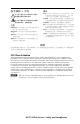
Table of Contents Chapter One • Introduction ..................................................... 1-1 About this Manual ..................................................................... 1-2 The MLC 104 Plus Series MediaLink™ Controllers ............ 1-2 Differences between models ................................................. 1-2 About Global Configurator ..................................................... 1-4 System Requirements .............................................................
Table of Contents, cont’d Step nine: assign serial device drivers ................................. 3-14 Step ten: assign IR drivers .................................................... 3-15 Step eleven: configure the front panel ............................... 3-16 Button caption ......................................................................3-16 Button tool tip .......................................................................3-16 Button repeat rate ...........................................
MLC 104 Plus Series 1 Chapter One Introduction About this Manual The MLC 104 Plus MediaLink® Controllers About Global Configurator Global Configurator Online Training
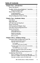
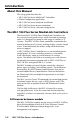
Introduction About this Manual This setup guide describes the • MLC 104 Plus Series MediaLink® Controllers • Global Configurator application • MLC 104 Plus Series hardware installation • MLC 104 Plus Series device connections • MLC 104 Plus Series software configuration The MLC 104 Plus Series MediaLink Controllers The Extron MLC 104 Plus Series MediaLink Controller is an easy-to-use control panel for any small classroom or meeting room. It is designed to control a wide range of smaller A/V systems.
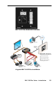
MLC 104 IP Plus MediaLink Controller TCP/IP Network Help Desk PC RS-232 or IR Projector control 1 VIDE Y LA SP DI 2 ME LU VO 4 FIG E AG IM TE MU C ML Ex LE EB TR SS BA LE REO STE VE L WE I PO MIN 2 12 MPAPLIFI ER R AM Audio ITE R Projector input switching L DUA O MON OFF Projector volume control RGBHV Extron SI 3CT LP US PL n tro MediaLink™ Controller with IP Link Projector on/off control Audio ON LIM 4 IP 10 Extron MLC 104 IP Plus S-Video Video Mini Power Amplifi
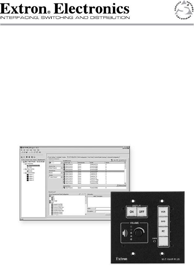
Introduction, cont’d About Global Configurator Global Configurator (GC) is a software application that gives users the ability to create a single configuration file of all of the controlled devices on their audio/video (A/V) network. There are two types of devices in an A/V system: Controllers - Control devices that have serial, relay, I/O, and infrared (IR) ports for A/V device connectivity; and, for MLC 104 IP Plus models, an IP Link enabled Ethernet port for network connectivity.
Using GC you can configure a single room controller, or create a web-based remote monitoring system for hundreds of A/V devices in multiple locations. You may configure an MLC using GC without having the device physically connected to the A/V network. N For MLC 104 IP Plus models, use Global Configurator version 2.2 or later. For MLC 104 Plus models, use version 2.5 or later. Update all PCs and devices running earlier versions of GC.
Introduction, cont’d To install Global Configurator from an Extron Software Products CD if Autorun is enabled on your PC: 1. Insert the Extron Software Products CD into your drive. 2. Wait for the Extron Software Products page to load. 3. Click on the Software icon. 4. Scroll down to the Global Configurator description and click the Install link in the far right column. 5. Follow the remaining system prompts.
MLC 104 Plus Series 2 Chapter Two Hardware Setup Front Panel Right Side Panel Left Side Panel and Top Panel Power Connection LAN Connection Front Host Configuration Port Device Connection
Hardware Setup Front Panel Front panel controls must be configured using the Global Configurator application (described in chapter 3) before they become functional. a b c d Display On/Off buttons — Use to turn the connected display device on and off. Input selection buttons — Use to select the desired audio and video input to the display device. Buttons light and remain lit when selected. Volume knob and LEDs — Use this knob to adjust the audio volume.
Right Side Panel Connectors on the unit's right side panel are described below. a b c d e f Display RS-232 / IR port — Dedicated bidirectional port for communication to a projector or display via RS-232 and/or infrared control.
Hardware Setup, cont’d Left Side Panel and Top Panel Controls on the left side panel and top panel are described below. a b c Reset Button — Recessed button used to reset the device. See the MLC 104 Plus Series Reference Manual for available reset modes. Reset LED — Green LED that flashes to indicate reset mode. IR Learning Sensor — Receives and “learns” infrared commands from other devices' remote controls to create an IR driver. Accepts infrared signals from 30 kHz to 62 kHz.
Power Connection To connect the external 12 VDC power supply: 1. Strip the ends of the power supply wires as shown in the diagram below. 2. Connect the stripped wires to the MLC's PWR port as shown in the diagram below. 3. Connect the AC power cord between the power supply and an AC power outlet.
Hardware Setup, cont’d LAN Connection (IP Models Only) Connect a straight-through Ethernet cable to the LAN connector if you are connecting to a switch, hub, or router on your network. Connect a crossover Ethernet cable to the LAN connector if you are connecting directly to a PC.
Front Panel Host Configuration Port A 2.5 mm mini stereo jack the provides an RS-232 connection for configuration and control. Use Extron configuration cable part #70-335-01 (9-pin D female to 2.5 mm TRS) to connect a control PC to this port. N The MLC 104 Plus (units without a LAN connection) can be configured only by this method.
Hardware Setup, cont’d Device Connections The following illustrations show examples of A/V and control device connections for all models. Display connection Transmit (Tx) Receive (Rx) Ground ( ) Transmit (Tx) Receive (Rx) Ground ( ) Projector Panel IR OUT Tx Rx GROUND Bidirectional DISPLAY RS-232/IR MLC 104 Plus Series Right Side Panel Infrared (IR) connection IR Emitter 1 G = Ground S = Signal (IR) White Striped Wire IR OUT Tx Rx GROUND 100' (30.
Comm Link connection SCP 104 A +12 VDC B Ground ( ) C IRCM, ACM, RCM, CM DISPLAY ON OFF VCR 1 DVD 2 PC 3 E SCP communication (IR) +V OUT GROUND CM IR IN SCP VOLUME CONFIG 4 A B C D E COMM LINK MLC 104 Plus Series Right Side Panel Maximum = 2 SCPs Per System SCP 104 C IRCM, ACM, RCM, CM B Ground ( ) A +12 VDC DVD & VCR CONTROL Maximum = 4 Control Modules (4 module addresses) 200' (61 m) max.
Hardware Setup, cont’d 2-10 MLC 104 Plus Series • Hardware Setup
MLC 104 Plus Series 3 Chapter Three Software Setup Creating a Global Configurator Project File Configuring a New Device Testing the GlobalViewer™ Pages
Software Setup Creating a Global Configurator Project File After you have installed Global Configurator (GC) software on your PC, follow the steps in this chapter to configure your devices. N For MLC 104 IP Plus models, use Global Configurator version 2.2 or later. For MLC 104 Plus models, use version 2.5 or later. Step one: download device drivers Software drivers for your audio/video devices are available free from the Extron web site at www.extron.com. To download device drivers: 3-2 1.
5. Click the Right Arrow (Subscribe) button. 6. Repeat steps 3 through 5 for each type of device you plan to add to your audio/video network. 7. Click the Download button. The Download Complete dialog box opens. 8. Click the Close button. 9. Click OK to return to the Start Options dialog box.
Software Setup, cont’d Step two: create a new project To create a new Global Configurator project file: 1. Select Create a New Project. 2. Click OK. The Project Settings dialog box opens. For IP models 3. For IP models, enter the IP address of the first device you will add to your GC project file in the Next Assigned IP Address field. 4. 3-4 Make the desired Date/Time selections.
5. Click OK. The Add Device dialog box opens. For an MLC 104 Plus (non-IP model) 3. Click Cancel. The Add Device dialog box opens.
Software Setup, cont’d Step three: add a device and set up its connection For IP models For IP models, obtain the following information from your network administrator: • IP address / hostname • gateway IP • subnet • Telnet port • web port • passwords 3-6 1. Select MLC 104 IP Plus Series from the IP Link Device drop-down list. 2. Enter an IP Address in the Name/IP Address field (or leave the default address). 3. Enter a unique Display Name. 4.
6. If the device you are adding is password protected, enter the appropriate Admin and User passwords. The default condition is no Admin or User password. 7. Click Auto Configure IP Address. 8. Enter the device’s MAC address (found on a label on the rear of the device). 9. Click Set. The Auto Configure Successful dialog box is displayed. 10. Click OK.
Software Setup, cont’d For an MLC 104 Plus (non-IP model) 1. Select MLC 104 Plus Series from the IP Link Device dropdown list. 2. 3-8 Click OK.
Step four: define the location of the new device (IP models only) Global Configurator allows you to keep track of the devices on your audio/video network by creating a custom tree of folders in which you can place and organize your audio/video devices. This GlobalViewer Tree can be up to eight levels deep and have multiple folders in each level. To move your newly added device to a location folder, with the Add Device dialog box still open: 1.
Software Setup, cont’d Step five: save the new Global Configurator file To save the new GC project file: 1. Click File > Save - or - click the Save icon. If the file has not previously been saved, the Save As dialog box opens. 3-10 2. Enter a unique name in the Project Name field. 3. Click the browse button to browse to the desired file location. 4. Click OK.
Configuring a New Device Step six: configure e‑mail server (IP models only) Obtain the following from your network administrator: • Mail server IP • Mail server domain • SMTP username and password N Device must be online to change device settings. To set the e-mail server configuration: 1. Click Tools > Change Device Settings... The Device Settings window opens. 2. Select a device. 3. Click Settings > Set Mail Server... The Mail Server dialog box opens. 4.
Software Setup, cont’d Step seven: configure e‑mail messages (IP models only) The Email Manager dialog box is used to create custom e-mails that are delivered as directed by the settings in the GC Schedule and Monitor dialog boxes. To create custom e-mails: 3-12 1. Click Edit > Email Manager... 2. Complete the Name, Subject, and Body fields. 3. Click Add. 4. Repeat steps 2 and 3 for each new e‑mail message. 5. Click Done.
Step eight: configure contacts (IP models only) The Contact Manager dialog box is used to enter the name, e-mail address, and company name of the network’s contacts. To configure contacts: 1. Click Edit > Contact Manager... 2. Complete the Name, Email, and Company fields. 3. Click Add. The contact information is added. 4. Repeat steps 2 and 3 for each additional contact. 5. Click OK.
Software Setup, cont’d Step nine: assign serial device drivers The Serial Configuration tab of Global Configurator allows you to assign a device driver to each serial port of the device. To assign a device driver: 1. Select a serial port in the IP Link Tree window. The Serial Configuration tab opens. 3-14 2. Select Serial in the Port Type field. 3. Select a device type, manufacturer, and version. 4. Select an available driver. 5. Click Add Driver. 6.
Step ten: assign IR drivers The IR Configuration tab of Global Configurator allows you to assign a device driver to each IR port of the device. To assign an IR device driver: 1. Select an IR port in the IP Link Tree window. 2. The IR Configuration tab opens. Select IR in the Port Type field. 3. Select a device type, manufacturer, and version. 4. Select an available driver. 5. Click Add Driver.
Software Setup, cont’d Step eleven: configure the front panel The Front Panel tab provides a graphical representation of the MLC's front control panel. It gives you the ability to: • Configure the operations of the front control panel buttons • Configure the captions and functions of the control buttons that are displayed in the GlobalViewer interface. Button caption A caption can be set for each button in the front panel display. To set a button caption: 1. Select a control button. 2.
Button repeat rate The repeat rate is how quickly a button will repeat its function if the button is held down. Example: If you have configured a button as an increment volume button, and given it a repeat rate of 1.00 second, as long as you keep this button pressed (the front panel button or the GlobalViewer button) the “increment volume” command will be sent every 1.00 second. To set a repeat rate: 1. Select a control button. 2. Select a rate from the Repeat Rate drop-down list.
Software Setup, cont’d Button modes The Set Button Modes options allow the user to apply three different modes of operation for all buttons on the MLC's front panel. Button modes of operation are: • Single Switch — the pushbutton switch performs the same function each time it is pressed. • Toggle — you can assign two different actions to subsequent depressions of the same pushbutton.
Switcher input The Switcher Input field allows you to assign a specific input from an attached MediaLink Switcher (MLS) to a specific input button on the MLC’s front panel (only applies to a button in input mode). To assign a switcher input: 1. Select one of the four input buttons. 2. Select a switcher input number from the drop-down list.
Software Setup, cont’d Button operations Selected functions in the Button Operations area of the window are moved to the Press, or Release windows to be assigned to the press or release action of the selected button. Tabs in the Button Operations area include: • Driver • Time Delay • User Defined • Light Control To assign a driver function to a button: 1. Select a button. 2. Click the Button Operations Driver tab. 3. Select a device and expand its folder (click the + sign). 4.
When you add multiple functions to a front panel button, you may want to insert a time delay between the functions. The Button Operations Time Delay tab provides the capability to add a delay of from 1 second to 180 seconds to the press or release action of a button. To add a time delay: 1. Select a front panel button. 2. Click the Button Operations Time Delay tab. 3. Expand the Time Delay function (click the + sign). 4. Enter the desired number of seconds (1 - 180) in the Wait field. 5.
Software Setup, cont’d The Button Operations User Defined tab allows users to add button functionality that is not predefined by entering ASCII strings or Extron Simple Instruction Set (SIS™) commands in the Command field and moving those commands to the Press window or the Release window. The User Defined tab is only functional with serial ports. For a listing of ASCII codes, click View > View ASCII Chart. To add a user defined command: 1. Select a front panel button. 2.
The Button Operations Light Control tab allows users to assign an indicator color to the Press and Release actions of selected buttons. Color changes are reflected on both the physical front panel button and the virtual front panel button in the GlobalViewer® interface (only applies to buttons in single switch or group mode). Indicator color options are: • Off • Green • Red • Amber Indicator blink options are: • No Blink • Slow Blink • Fast Blink To assign an indicator color to a button: 1.
Software Setup, cont’d Clear, reset, and auto fill captions Use the Clear button to clear all front panel button caption text. Use the Reset button to delete all operations on the front panel buttons and reset the captions to their factory default text. The Auto Fill button is not active on the front panel tab. It is active on the Address tab when a control module is selected in the IP Link Tree window.
Step twelve: configure associated control modules A control module is a faceplate with buttons that can be associated with the MLC. The buttons on a control module can be configured to perform specific device operations, such as power on a device or raise/ lower audio volume. The Control Module Summary tab is used to configure the button operations of a control module. To configure a control module: 1. Select a control module address in the IP Link Tree window.
Software Setup, cont’d 2. Select an available control module. 3. Click the Add (right arrow, ) button. The new control module is displayed in the Control Module Summary field and in the IP Link Tree window. 3-26 4. Select the newly assigned control module's Address in the IP Link Tree window. 5. Select the desired button on the control module and add button operations as described in “Step eleven: configure the front panel.
Step thirteen: create a shutdown schedule Global Configurator’s scheduling feature enables you to schedule specific actions to occur for a selected device. As an example, scheduling is useful to set network projectors to power off at the end of the day to prevent idle lamp usage. To set a display shutdown schedule: 1. Click the Schedule tab. 2. Click the Add Schedule button.
Software Setup, cont’d 3-28 3. Enter a unique name in the Schedule Action Name field. 4. Set the desired schedule times. 5. Click Next. 6. Select the desired Subject Port (device). 7. Select the Available Option Power Control - Off. 8. Click Apply Action. 9. Click Done.
Step fourteen: create a lamp hour notification (IP models only) Global Configurator’s monitoring feature enables you to configure IP Link devices to monitor many parameters of their connected audio/visual devices. This feature can be used to monitor lamp usage hours and send an e‑mail alert to the network administrator if a display’s lamp is nearing expiration. To create a display (projector) lamp hour warning e‑mail: 1. Click the Monitor tab. 2. Click the Add Monitor button.
Software Setup, cont’d 9. 10. 11. Select a subject port or device. Select Available Options Lamp Usage: Value. Select Is Greater or Equal in the Display: Lamp Usage Value field. Enter a number (hours) that is less than the lamp’s anticipated burn-out spec in the Lamp Usage Value field. Click Apply Condition. Click Next. Click Next a second time to add an e‑mail notification. 12. 13. 14. 15. Select Email Messages Excessive Lamp Hours. Select the desired contacts. Click Apply Email/Contacts. Click Done.
Step fifteen: create a disconnect notification (IP models only) Global Configurator’s monitoring feature enables you to configure IP Link devices such as an MLC 104 IP Plus to monitor many parameters of their connected audio/visual devices. This feature can be used to monitor a display connection and send an alert e‑mail to the administrator if a display is unexpectedly disconnected from the network. To create a display disconnection e‑mail alert: 1. Click the Monitor tab. 2.
Software Setup, cont’d 3-32 5. Select a subject port or device. 6. Select Available Options Connection Status: Disconnected. 7. Click Apply Condition. 8. Click Next. 9. Click Next a second time to add an e‑mail notification. 10. Select Email Messages Disconnect Notification. 11. Select the desired contacts. 12. Click Apply Email/Contacts. 13. Click Done.
Step sixteen: build the Global Configurator file Before a Global Configurator (GC) file is active in the GlobalViewer interface, the GC file must be “built” and uploaded to a GlobalViewer host device. The “build” process compiles all of the configuration data you have entered into the GC file for each A/V network device. The upload process delivers the built (compiled) file to the GlobalViewer host device. To initiate a “Build (all)” process: 1. Click Build > Build All Configurations...
Software Setup, cont’d Step seventeen: upload the Global Configurator file When the build process completes, the Upload dialog box opens. 3-34 1. Click the Begin button. When the upload process completes, the Progress and Status fields are updated to indicate completion. 2. For IP models only, click the Test GV System button to view the GlobalViewer host interface.
Step eighteen: launch GlobalViewer (IP models only) GlobalViewer is a graphical user interface that is generated by Global Configurator (GC). When a GC file is built and uploaded to a GlobalViewer host device, you can launch the GlobalViewer interface by opening an Internet browser and entering the host device’s IP address in the browser's address field. Once the GlobalViewer interface is launched, you can monitor and control all of the devices on your audio/video network from the GlobalViewer host device.
Software Setup, cont’d Testing the GlobalViewer pages Use the GlobalViewer graphical user interface (IP models only), the MLC’s front panel, and, if present, the buttons on an associated control module to test for proper operation of the MLC and any connected devices. More information on operation and testing of the MLC and its connected devices can found in the MLC 104 Plus Series User's Manual, part number 68-1443-01, which can be downloaded from www.extron.com.
Extron’s Warranty Extron Electronics warrants this product against defects in materials and workmanship for a period of three years from the date of purchase.
Setup Guide Checklist c Chapter 1: Install Global Configurator • Download from www.extron.com, or c • Install from Extron Software Products CD Chapter 2: Make the MLC cable connections. 1. c Power 2. c Local Area Network (LAN) – IP models only 3. c Devices Chapter 3: Configure MLC 104 Plus Series using Global Configurator. c 1. c Download device drivers. 2. c Create a new Global Configurator project file. 3. c Add a device and (for IP models) set its IP address.