
Setup guide
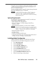
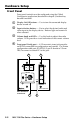
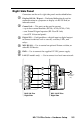
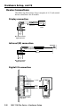
Table Of Contents
- Front cover
- Safety Precautions
- Safety Precautions (Chinese) and FCC Class A Notice
- Table of Contents
- Ch. 1: Introduction
- Ch. 2: Hardware Setup
- Ch. 3: Software Setup
- Creating a Global Configurator Project File
- Configuring a New Device
- Step six: configure e‑mail server (IP models only)
- Step seven: configure e‑mail messages (IP models only)
- Step eight: configure contacts (IP models only)
- Step nine: assign serial device drivers
- Step ten: assign IR drivers
- Step eleven: configure the front panel
- Step twelve: configure associated control modules
- Step thirteen: create a shutdown schedule
- Step fourteen: create a lamp hour notification (IP models only)
- Step fifteen: create a disconnect notification (IP models only)
- Step sixteen: build the Global Configurator file
- Step seventeen: upload the Global Configurator file
- Step eighteen: launch GlobalViewer (IP models only)
- Testing the GlobalViewer pages
- Warranty
- Back cover:checklist and contact information
MLC 104 Plus Series • Hardware Setup
Hardware Setup, cont’d
2-6
LAN Connection (IP Models Only)
Connect a straight-through Ethernet cable to the LAN connector
if you are connecting to a switch, hub, or router on your
network.
Connect a crossover Ethernet cable to the LAN connector if you
are connecting directly to a PC.
2
3
GROUND
1
IR IN
GROUND
IR OUT
CM
SCP
GROUND
GROUND
Tx
Rx
DISPLAY
RS-232/IR
LAN
PRESS TAB WITH
TWEEKER TO REMOVE
A B
MLS PWR
RS-232 12V
DIGITAL
I/O
A B C D E
COMM LINK
+V OUT
GROUND
Tx
Rx
+12V IN
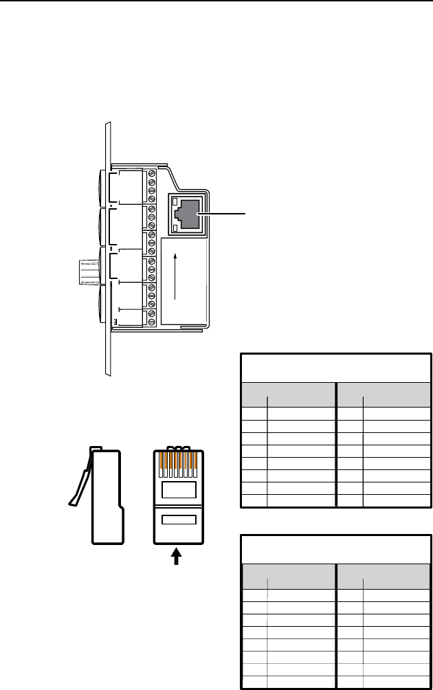
LAN
Connector
12345678
RJ-45 Connector
Insert
Twisted
Pair Wires
Pins:
Side View
Straight-through Cable
(for connection to a switch, hub, or router)
End 1 End 2
Pin Wire Color Pin Wire Color
1 white-orange 1 white-orange
2 orange 2 orange
3 white-green 3 white-green
4 blue 4 blue
5 white-blue 5 white-blue
6 green 6 green
7 white-brown 7 white-brown
8 brown 8 brown
Crossover Cable
(for direct connection to a PC)
End 1 End 2
Pin Wire Color Pin Wire Color
1 white-orange 1 white-green
2 orange 2 green
3 white-green 3 white-orange
4 blue 4 blue
5 white-blue 5 white-blue
6 green 6 orange
7 white-brown 7 white-brown
8 brown 8 brown