Quick Start Guide MLC 52 Series MediaLink™ Controller 68-1184-01 Rev.
Precautions Safety Instructions • English Warning This symbol is intended to alert the user of important operating and maintenance (servicing) instructions in the literature provided with the equipment. Power sources • This equipment should be operated only from the power source indicated on the product. This equipment is intended to be used with a main power system with a grounded (neutral) conductor. The third (grounding) pin is a safety feature, do not attempt to bypass or disable it.
MLC 52 Series Quick Start Guide About the MLC 52 Series The Extron MediaLink™ Controller 52 (MLC 52) provides infrared (IR) and/or RS-232 remote control of a projector or other display device. It is an economical, compact (one-gang size), easy-to-use controller designed for use with audiovisual equipment in sites such as an elementary or high school classroom, or a small conference room.
MLC 52 Series Quick Start Guide, cont’d MLC 52 VC models with volume control faceplate The two-gang sized MLC 52 IR VC and MLC 52 RS VC each have a projector volume control knob in addition to the six control buttons. To use this knob, you must connect the MLC 52 to an Extron MPA Series Mini Power Amplifier (sold separately), to which you can also connect the projector (see the application diagram below).
Installing the MLC 52 The MLC can be installed into a wall or furniture. Follow the instructions appropriate to the mounting option you have selected. Step 1 Prepare the installation site as required for your MLC model (cut a hole in the wall or furniture, and install an electric wall box and/or mounting bracket). See “Mounting an electrical box” in chapter 2, “Installation,” of your MLC 52 User’s Manual, for details on this procedure. a.
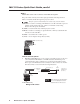
MLC 52 Series Quick Start Guide, cont’d Step 3 Attach cables to the control connector on the MLC 52 rear panel. The ports in this connector, from left to right, perform the following functions: F (Tx) — Transmits the RS-232 signal for projector control. This port is present on all models, but it is active only on the RS models. E (IR OUT) — Used for connecting an IR Emitter to issue IR commands. Up to two emitters can be wired to this port.
b. Wire the RS-232 (Tx) port (RS models only). If you have an RS model and want to control the projector via RS-232, connect a cable between the projector and this 3.5 mm, 6-pole direct insertion captive screw connector. Use the following illustration as a guide. Refer to “Wiring for RS-232 control” in chapter 2, “Installation,” of your MLC 52 User’s Manual, for details on cable pin assignments and the wiring procedure.
MLC 52 Series Quick Start Guide, cont’d VOL/ MUTE 10V VOL 10V MLC 52 VC potentiometer Rear Panel 1 2 10V VOL 3 MPA 122 or MPA 181T Remote Port Wiring the VC potentiometer to the MPA remote volume control port Step 4 Attach cables to the projector and, optionally, the IR Link, the IR Emitter, and/or the IRL 20. Step 5 Connect power cords and turn on all the devices, including the MLC.
AY PL DIS F OF ON PC Wall opening is flush with edge of box.
MLC 52 Series Quick Start Guide, cont’d Step 3 Press the button on the MLC front panel that will store the IR code that you want the MLC to learn. The following takes place on the MLC: • The button that you pressed begins to blink, indicating that it is ready to be programmed. While the button is blinking (5 seconds), you can program the button with the desired command. • On the rear panel, the IR Learning LED that indicates the button memory block currently available for programming begins to blink.
Step 6 When finished programming buttons, set configuration switch #1 on the rear panel to Off. Verify that the commands you entered have been learned by pressing the buttons that you programmed. Removing commands from a button If you want to delete one or more commands that have been programmed onto a button, you must remove all the commands programmed to that button. Follow these steps: 1. While the MLC 52 is powered on, make sure that configuration DIP switch #1 is set to On. 2.
MLC 52 Series Quick Start Guide, cont’d Tx IR OUT 1 GND IR IN GND + 12V Less Than 6” 1 2 3 4 2 3 ON 4 E E 4 3 IR Beaming ON 2 + 12V GND IR IN 1 2 3 4 GND IR OUT Tx 1 ON 1 2 3 4 Transmitting MLC ON 1 2 3 4 Receiving MLC Setting up donor and receiver units for wireless data transfer The illustrations show the standard (1-gang sized) MLC 52. However, the procedures are the same for the VC models.
DISPLAY ON VOL VOL OFF PC VIDEO MLC 52 Order in which the buttons blink during data transfer After each 17% of the data has been transferred, the next button in the order of lights remains lit brightly. This continues until the transfer process is complete and all buttons are permanently lit. By observing how many buttons are lit steadily, you can see approximately how much data has been transferred. The buttons on the MLC VC models blink in the same pattern as the standard models.
MLC 52 Series Quick Start Guide, cont’d To Front Panel Config Port MLC 52 6 feet (1.8 m) DISPLAY ON 1 5 OFF Part #70-335-01 6 9 PC VOL Tip Ring Sleeve (Gnd) Computer 9-pin D Connection TRS Plug Pin 2 Pin 3 Pin 5 Computer's RX line Computer's TX line Computer's signal ground Tip Ring Sleeve VOL VIDEO MLC 52 2.5 mm Configuration Port 2.5 mm connector cable for the configuration port The included CD contains the configuration software and various projector/ display drivers.
Powering off To turn the projector/display off, press the Off button. The button blinks for 4 seconds, then remains steadily lit. The power On and Off buttons blink while the projector is warming up and cooling down. The warm-up and cool-down delay periods can be changed via the Windows-based configuration software. Locking the Front Panel (Executive Mode) When the MLC 52 is in executive mode, all front panel functions are locked, so that pressing them has no effect.
www.extron.com Extron Electronics, USA 1230 South Lewis Street Anaheim, CA 92805 800.633.9876 714.491.1500 FAX 714.491.1517 Extron Electronics, Europe Beeldschermweg 6C 3821 AH Amersfoort, The Netherlands +800.3987.6673 +31.33.453.4040 FAX +31.33.453.4050 Extron Electronics, Asia 135 Joo Seng Rd. #04-01 PM Industrial Bldg., Singapore 368363 +800.7339.8766 +65.6383.4400 FAX +65.6383.4664 © 2007 Extron Electronics. All rights reserved.