User Guide MediaLink Accessories MLM 52 1GWP MLM 52 VC Wall Mounting Kits for MLC 52 Controllers 68-1161-01 Rev.
Safety Instructions • English Warning This symbol is intended to alert the user of important operating and maintenance (servicing) instructions in the literature provided with the equipment. Power sources • This equipment should be operated only from the power source indicated on the product. This equipment is intended to be used with a main power system with a grounded (neutral) conductor. The third (grounding) pin is a safety feature, do not attempt to bypass or disable it.
FCC Class A Notice This equipment has been tested and found to comply with the limits for a Class A digital device, pursuant to part 15 of the FCC rules. The Class A limits provide reasonable protection against harmful interference when the equipment is operated in a commercial environment. This equipment generates, uses, and can radiate radio frequency energy and, if not installed and used in accordance with the instruction manual, may cause harmful interference to radio communications.
Contents Introduction............................................................ 1 About this Guide ................................................. 1 About the MLM 52 ............................................. 1 Application Diagrams ........................................... 2 Installation.............................................................. 3 Attaching the Controller to the Faceplate ............. 3 MLM 52 1GWP ................................................ 3 MLM 52 VC .................
MLM 52 Wall Mounting Kits • Contents vi
Introduction This section gives an overview of the MLM 52 Series faceplates. Topics include: • About this Guide • About the MLM 52 • Application Diagrams About this Guide This guide describes the Extron MLM 52 Series faceplates and discusses how to attach MLC 52 controllers to them. It also provides procedures for installing the MLM 52 in a wall or furniture. In this guide, the terms “MLM” and “MLM 52” refer to both the MLM 52 1GWP and the MLC 52 VC, and are used interchangeably.
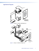
Application Diagrams IR or RS-232 Control DI SP Y LA F OF ON Projector with Internal Speakers PC L VO EO VID L VO ML 2 C5 Extron MLM 52 1GWP with MediaLink® Controller Installed PC DVD Figure 1.
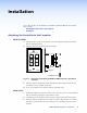
Installation This section describes the installation of the MLM 52 1GWP and MLM 52 VC faceplates. Topics include: • Attaching the Controller to the Faceplate • Installation Attaching the Controller to the Faceplate MLM 52 1GWP 1. Remove the three screws (located at the rear of the original faceplate) that hold the MLC 52 controller in place. 2. Carefully remove the controller from the faceplate. DISPLAY ON VOL VOL OFF PC VIDEO Standoff MLC 52 Faceplate Use supplied screws. Figure 3.
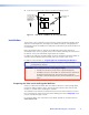
4. Secure the faceplate in place with the provided self-tapping screws. Secure the MLC 52 controller and the VC module onto the stand-offs using self-tapping screws for plastic plates. Figure 4. Standoffs for the VC Module Rear View of MLM 52 VC, Showing Standoffs Installation The faceplates can be installed in a wall or furniture using a standard one-gang electrical wall box or mounting bracket (mud ring) for the MLM 52 1GWP, or a two-gang box or mounting bracket for the MLM 52 VC.
1. If a wall box is not available for marking the mounting hole, create a full-scale template with the dimensions shown in the “Templates and Dimensions” section (beginning on page 7). Cut out the center portion of the template you created. 2. Place the template (or the wall box) against the installation surface, and mark the opening on the wall or furniture. 3. Cut out the material from the marked area. 4. Check the size of the opening by inserting the wall box into it. The box should fit easily.
5. Turn the two screws on the bracket so that the locking arms rotate behind the mounting surface until they clamp securely to it. Do not overtighten. Wall Wall Wall Mounting Bracket Wall Mounting Bracket Figure 6. Attaching a Mounting Bracket to the Mounting Surface 6. Run the required cables from the wall or furniture through the mounting bracket to the MLC 52 and attach them. 7.
Templates and Dimensions For assistance with mounting the MLM 52 faceplates, this section contains templates (not to scale) for cutting holes in walls or furniture. It also provides diagrams showing the dimensions of the two faceplate models. Topics include: • MLM 52 1GWP Template • MLM 52 1GWP Dimensions • MLM 52 VC Template • MLM 52 VC Dimensions NOTE: The templates are not to scale. Full size cut-out templates are available online at www.extron.com.
MLM 52 1GWP Dimensions 2.8” (7.1 cm) 0.68” (1.72 cm) 4.5” (11.4 cm) 0.19" (0.48 cm) MLM 52 VC Template Cut-Out Template for the Extron MLM 52 VC (Front View) 4.60" (11.68 cm) Top Panel 3.50" (8.90 cm) 4.50" (11.43 cm) 2.83" (7.19 cm) SURFACE CUT-OUT AREA FOR FURNITURE MOUNT Location of MLC 52 To install the MLM 52 VC directly into furniture or wall, cut along this line.
MLM 52 VC Dimensions 4.6” (11.7 cm) 0.68” (1.72 cm) 4.5” (11.4 cm) 0.19" (0.
Extron Warranty Extron Electronics warrants this product against defects in materials and workmanship for a period of three years from the date of purchase.