MLM-WB MediaLink Wall Box Mounting Option 68-608-01 Printed in the USA
Precautions Safety Instructions • English This symbol is intended to alert the user of important operating and maintenance (servicing) instructions in the literature provided with the equipment. This symbol is intended to alert the user of the presence of uninsulated dangerous voltage within the product's enclosure that may present a risk of electric shock. Warning Power sources • This equipment should be operated only from the power source indicated on the product.
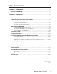
Table of Contents Chapter 1 • Introduction ....................................................................................................... 1-1 About the MLM-WB ............................................................................................................ 1-2 Chapter 2 • Installation .......................................................................................................... 2-1 Installation Overview ........................................................................
Table of Contents, cont’d ii MLM-WB • Table of Contents
MLM-WB 1 Chapter One Introduction About the MLM-WB
Introduction About the MLM-WB The Extron MLM-WB is a metal wall box for housing a user-supplied MediaLink™ Controller (MLC), a VCR, and up to eight single space Architectural Adapter Plates (AAPs) or AAP devices. You can securely mount a VCR in the wall box, and you select the direction (left or right) the front of the VCR faces. A laptop or other small, external device can be placed on the MLM-WB’s fold-down shelf.
MLM-WB 2 Chapter Two Installation Installation Overview UL Requirements Identifying Included Parts and Hardware Mounting the MLM-WB Installing a VCR Installing the Door Installing AAP Devices and a MediaLink Controller Completing and Testing the Installation Attaching the Shelf
Installation Installation Overview CAUTION Installation and service must be performed by Extron authorized personnel or a qualified electrician only. 1 Unpack and locate the MLM-WB’s parts and hardware. See “Identifying Parts and Hardware” on page 2-4. 2 Select the installation site. On non-masonry walls the MLM-WB must be attached to at least one stud. The installation is sturdiest if the wall box is attached to two wall studs or to a concrete/masonry wall.
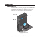
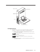
Mounts to Wall AAP Openings M Li ia ed nk p La pto D DV R VC LAY DISP ER POW UME VOL MAX/ MIN MLC 206 Ex tro n VCR Fold Down Shelf (Fold when not in use.) UL Requirements The Underwriters Laboratories (UL) requirements listed below pertain to the installation of a MediaLink Controller (MLC) into an MLM-WB wall box. 1. The MLC is not to be connected to a centralized DC power source or used beyond its rated voltage range.
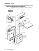
Installation, cont’d Identifying Included Parts and Hardware The MLM-WB is shipped partially assembled. You must unfasten and remove some parts before you can mount the enclosure to the wall or install the VCR. Refer to the diagrams below as you unpack the MLM-WB and prepare to install it.
Enclosure mounting hardware (6) 1/4" x 1 3/4" Masonry Screws #40-373-01 (4) 1/4-20 x 2" Pan Head Bolts #40-375-01 (6) #14 x 1 3/4" Self-tapping Metal/Wood Screws #40-372-01 (4) 1/4" Kap Toggle Assemblies #40-374-01 (6) 1/4" x 1" O.D., 5/16" I.D.
Installation, cont’d Before mounting the MLM-WB to a wall, remove the following parts and set them and the screws, nuts, and washers in a safe place: • the door (remove the hex screws and washers from the hinge points) • the top and front VCR clamp plates (remove the whole set as a unit by removing three screws from the bottom of the outer enclosure and removing three nuts that attach the top clamp plate to the rear wall) • the VCR shelf (remove the five screws that secure it to the floor and rear wall of t
5. 6. For each slotted mounting hole ( ) for which you have drilled a pilot hole: a. Insert a provided masonry screw through a flat metal washer (1”, 2.5 cm outer diameter; 0.25”, 0.6 cm inner diameter). b. Insert the screw into the pilot hole. c. Securely fasten each screw (or toggle bolt) into the wall until a gap of 1/8” (3 mm) remains between the wall and the metal washer.
Installation, cont’d the enclosure and observe the bubble in the horizontal tube. It will be in the center of the tube when the enclosure is level.) • If two wall studs are accessible where the MLM-WB will be installed, align the mounting holes with the studs, and mark at least six locations for self-tapping metal/wood screws, as shown (as + marks) in the pictures below at left and center. 16" (40.6 cm) 12" (30.
1 2 3 4 Inserting the Toggle Kap (1), securing it with the plastic washer (2), removing the plastic handle (3), and attaching the washer & screw (4) 7. Align the slotted mounting holes in the back of the MLM-WB’s outer enclosure with the screws and/or toggle bolts in the wall. Move the MLM-WB forward over the washers and down as shown in step seven of ”Installing the MLM-WB on a masonry wall” on page 2-7. 8.
Installation, cont’d 3. Place the junction box you plan to use against the front (refer to the picture below) of the international junction box mounting plate, and mark on the plate the locations for the junction box’s mounting screws. Set the box aside. 4. Drill pilot holes for the mounting screws in the marked (indicated by + in the illustration) locations on the mounting plate. 5. Fasten the new junction box to the mounting plate, hand tightening the screws. See the picture at right. 6.
Installing A/V and control cables To reduce electromagnetic interference, the audio/video (A/V) and control cables should be routed separately from the power supply cord. 1. Feed the A/V and control cables through the large rectangular opening in the MLM-WB’s rear panel or through the top of the enclosure (through an existing hole or a custom-made one). • If you route cables through the top of the MLM-WB, install a conduit through the remaining hole or a custom-made hole.
Installation, cont’d 3. Install the adjustable plates on the side that will be used for VCR access, if that has not already been done. Do not tighten the nuts yet. #632 Nut with Washer (3 places) Horizontal VCR Access Plate Vertical VCR Access Plate VCR Access Plates (top, front view from the inside of the MLM-WB) Loosely attach the vertical VCR access plate’s long or short face (depending on VCR size) to the side of the MLM-WB.
4. Align the holes in the VCR shelf with the posts on the floor and back wall of the MLM-WB, insert screws through the holes into the posts, and tighten the screws. VCR Shelf #440, 1/4" Flat Head Screws (5 places) 5. Set the VCR on its side on the VCR shelf so the VCR’s top faces the back of the MLM-WB, and the VCR’s front panel touches the desired side of the MLM-WB. Adjust the size of the side opening in the adjustable plates to securely fit the VCR, then tighten the nuts.
Installation, cont’d 6. Connect A/V cable(s) and a power cord to the VCR’s rear panel. For details, refer to the instructions that came with the VCR. Direct the A/V cable(s) up towards where A/V cables will enter and exit the enclosure. Direct the power cord up to the junction box. Make sure the cords will be out of the way of the front clamp plate that you will install in step seven. Do not connect the other ends of the cables to anything yet. 7.
9. Install and adjust the clamp plate assembly. 9a. Place the clamp plate assembly into the MLM-WB enclosure and route the VCR’s power and A/V cables around it, away from the bottom of the VCR, where the clamp plate will go. 9b. Align the holes in the top plate with the screw posts on the rear wall, and install and securely tighten the nuts. Align the holes in the base of the front plate with the slits in the bottom of the enclosure. Insert and loosely fasten the screws from the outside of the enclosure.
Installation, cont’d 9d. Loosen the screws and use a screwdriver to move the vertical clamp bracket against the rear panel of the VCR and to push the horizontal clamp bracket down against the VCR. Tighten the screws to fasten the brackets in place. The VCR should be snugly fastened in and should not move within the MLM-WB. If the VCR wiggles/shifts when touched, adjust the brackets and clamp plates so the VCR does not move when touched. Adjust top clamp bracket then tighten (3) #440 screws.
3. Insert the longer (1/8”, 0.3 cm long thread region) socket screws into the door hinge holes, and hand tighten them with the provided hex wrench. 4. Open and close the door to make sure you can still move it smoothly, and loosen or tighten the hex socket screws as needed. If the front of the VCR faces out the right side of the MLM-WB, when you open the door, becareful not to push the hinged side of the door against the face of the VCR.
Installation, cont’d • Make the cables long enough to allow the MLM-WB’s door to fully open once the MLC is installed in the door. • For connections to control modules that are installed in the MLM-WB’s door, cut the wires just long enough to reach from the MLC to the control modules, connect one end to the appropriate pins on the MLC, and connect the other to a captive screw connector.
5. Detach one of the preprinted labels or one of the blank labels from the sheet of labels that is included with the MLC. Remove the protective film from the front of the label. To create customized labels, use a label maker, such as a Brother P-touch, and clear label material to print text to place on the blank labels. 6. Insert the new label into the opening from which the other label was removed. 7. Repeat steps four through six for each label you wish to replace. 8.
Installation, cont’d 6. Disconnect power (outside the MLM-WB) from the MLC, and also from the input and output devices, and the host computer. The computer that was used for set up in step four may be disconnected from the MLC. 7. Secure the MLC’s external power supply to the top clamp plate, as shown below. Conduit MLC 206 Power Supply (Use hook-and-loop fasteners here.) Electrical Power Source 8.
Attaching the Shelf 1. Attach the shelf to the shelf bracket on the MLM-WB’s door. Use the provided #832, 3/16” hex socket screws and #832 nuts, as shown in the following illustration. M La DV LAY DISP ER POW Li ia ed nk ptop D R VCR VC UME VOL / MAX MIN t Ex n ro Shelf Bracket Shelf #832, 3/16" Hex Socket Screw (one on each side) #832 Nut (one on each side) When the shelf is not in use, fold the shelf down (out of the way) to prevent people from bumping into it and becoming injured.
Installation, cont’d 2-22 MLM-WB • Installation
MLM-WB A Appendix A Specifications, Part Numbers, Accessories, and Dimensions Specifications Part Numbers and Accessories Dimensions
Specifications, Part Numbers, Accessories, Dimensions Specifications General Enclosure type .............................. Metal Enclosure dimensions ................. 25.0” H x 18.6” W x 6.5” D (63.5 cm H x 47.2 cm W x 16.5 cm D) Depth is 8.6” (21.8 cm) including the folded shelf and bracket, 20.75” (52.7 cm) with the shelf extended. (Depth excludes controls and knobs of installed equipment.) Product weight ............................. 35.7 lbs (16.2 kg) Shipping weight ...........................
Accessories These items can be ordered separately: Miscellaneous accessories MLC 206 (3 gang) (gray, black, white) MLA-Remote IR remote control Part number 60-385-01, -02, -03 70-154-01 IR Link IR signal repeater (gray, black, white) 60-404-01, -02, -03 IRCM-VCR (gray, black, white) 70-148-01, -02, -03 IRCM-DVD (gray, black, white) 70-149-01, -02, -03 IRCM-DVD+ (gray, black, white) 70-179-01, -02, -03 IRCM-Tape (gray, black, white) 70-180-01, -02, -03 ACM-Tone (gray, black, white) 70-181-01, -0
MLM-WB • Specifications, Part Numbers,, Accessories, and Dimensions .000.000 MLM-WB dimensions .750" 3.250 3.250 4.005" 1.250 1.540 1.750 1.840 4.250 4.360 4.660 5.250 4.250 9.250 9.250 2.195" .000 1.750 6.750 7.250 6.750 7.250 11.250 11.750 11.250 11.750 A-4 13.250 18.150 18.150 18.500 16.750 17.250 16.750 15.250 15.250 14.250 14.250 6.250 4.000 .000 .250 1.644 24.25 24.900 24.99 20.000 15.438 8.750 4.500 5.950 6.525 1.625 2.450 3.900 4.200 .000 .100 .500 .250 .000 1.
Extron’s Warranty Extron Electronics warrants this product against defects in materials and workmanship for a period of three years from the date of purchase.
www.extron.com Extron Electronics, USA Extron Electronics, Europe Extron Electronics, Asia Extron Electronics, Japan 1230 South Lewis Street Anaheim, CA 92805 USA 714.491.1500 Fax 714.491.1517 Beeldschermweg 6C 3821 AH Amersfoort The Netherlands +31.33.453.4040 Fax +31.33.453.4050 135 Joo Seng Road, #04-01 PM Industrial Building Singapore 368363 +65.6383.4400 Fax +65.6383.4664 Daisan DMJ Building 6F 3-9-1 Kudan Minami Chiyoda-ku, Tokyo 102-0074 Japan +81.3.3511.7655 Fax +81.3.3511.