
User`s manual

Extron Electronics, USA
1230 South Lewis Street
Anaheim, CA 92805
USA
714.491.1500
Fax 714.491.1517
Extron Electronics, Europe
Beeldschermweg 6C
3821 AH Amersfoort
The Netherlands
+31.33.453.4040
Fax +31.33.453.4050
Extron Electronics, Asia
135 Joo Seng Road, #04-01
PM Industrial Building
Singapore 368363
+65.6383.4400
Fax +65.6383.4664
www.extron.com
Extron Electronics, Japan
Kyodo Building
16 Ichibancho
Chiyoda-ku, Tokyo 102-0082 Japan
+81.3.3511.7655
Fax +81.3.3511.7656
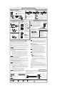
MLS 304MA MediaLink
™
Switcher
Control Connections
250 feet (76.2 m) maximum
MLS 304MA to an MLC
NOTE If you use cable that has a drain
wire, tie the drain wire to ground
at both ends.
MLC's
MLS/Power
port
Ground ( )
+12 VDC
Transmit (Tx)
B
Receive (Rx)
A
A B
MLS
/
Power
Transmit (Tx)
Receive (Rx)
+12 VDC
Ground ( )
B
A
RS-232
MLC/IR
MediaLink
Switcher's
RS-232/
MLC/IR
port
Tx Rx IR +12V
A B C
This RS-232 port is used to connect
the switcher to an MLC or a PC and to
configure the switcher via the supplied
MediaLink Control Software.
Mono Amplified Audio Output
down = 4 ohm or 8 ohm
direct connection
up = 70 V or 100 V transformer
70 V Distributed System
AMPLIFIED OUTPUT
20 WATTS MONO
DIRECT
XFMR
COM
4/8 ohm
100V
70V
Common 70 V
AMPLIFIED OUTPUT
20 WATTS MONO
DIRECT
XFMR
COM
4/8 ohm
100V
70V
Common 100 V
100 V Distributed System
AMPLIFIED OUTPUT
20 WATTS MONO
DIRECT
XFMR
COM
4/8 ohm
100V
70V
4 Ohm or 8 Ohm System
NOTE Both the toggle switch position and the
wiring must match the desired output type.
CAUTION Do not short output terminals to ground.
CAUTION The MLS 304MA integrates a class AB
amplifier. It will get warm.
Inputs 1 and 2
RCA (Tip-Ring) Connectors
Inputs 3 and 4
3.5 mm Stereo Plug Connectors
Sleeve (Gnd )
Tip (+)
Sleeve ( )
Right Channel
(Red Jacket)
Left Channel
(White Jacket)
Tip (Signal)
Sleeve ( )
Ring (R)
Tip (L)
Unbalanced
LINE LEVEL
MONO
+ Positive
– Negative
Ground
-10 dBV
sensitivity
Auxiliary/Mixer Input Connections
Non-amplified Audio Connections
The Aux/Mix input accepts a balanced or unbalanced
mono signal from various audio sources such as a
wireless microphone. Setting the potentiometer to
the marked location sets the input level sensitivity for
a -10 dBV (approximately) consumer signal.
NOTE The maximum auxiliary input signal level is
+4 dBu. Do not exceed this input level.
Use a small screwdriver to adjust the Aux/Mix level
(-42 dB to +24 dB) via the rear panel control.
Set the level to minimum if no input is
connected.
33-984-01 C
06 06
Balanced
Stereo Output
Unbalanced
Stereo Output
CAUTION
Connect the sleeve
to ground (Gnd).
Connecting the
sleeve to a
negative (–) terminal
will damage the
audio output circuits.
R
Left Tip
Sleeves
Right Tip
L
Left Ring
Right Ring
Lineout/Preamp
Mono Output
For mono output, wire
either the left or the
right side (not both).
Output level options:
• -10 dBV (0.316 Vrms),
unbalanced: default,
for consumer level
devices such as VCRs,
self-powered speakers,
and stereo receivers.
• +4 dBu (1.23 Vrms),
balanced: for
professional devices
such as mixers, signal
processors, and power
amps.
Left Tip
Sleeves
Right Tip
L R
See Caution.
See Caution.
Tip
NO GROUND HERE.
Sleeve(s)
Tip
NO GROUND HERE.
L R
CAUTION
For unbalanced audio, connect the sleeve(s)
to the center contact ground. DO NOT connect
the sleeve(s) to the negative (-) contacts.
Tip
Ring
Sleeve(s)
Tip
Ring
L R
MAX
MID
MIN
Signal: when lit this LED indicates that a signal of at
least -20 dBV (-18 dBu) is detected at the input.
Clip: if blinking/lit, the level is set too high.
Normal: a blinking LED indicates that the
level is set properly for max. power output.
Gain/attenuation
-42 dB to +24 dB
Tone
Bass: +/-10 dB at 100 Hz
Treble: +/-10 dB at 10 kHz
Loudness: +10 dB at 100 Hz/10 kHz
Sensitivity
-20 dBV (-18 dBu, 100mV)
Resetting to Defaults
These items are reset:
• audio level (sensitivity, -10 dBV)
• audio gain/attenuation (0 dB)
• bass and treble (0)
• loudness (off)
• line level out (stereo)
• video type (inputs 4-6 = RGB)
• RGB delay (0 sec.)
• Monitor Output mode
(RGB follow)
• executive mode (off)
To reset the switcher:
1. Unplug the switcher from AC power.
2.
Press and hold buttons 1 and 4
simultaneously while connecting
the MLS to AC power.
All input selection buttons blink for
one second while the MLS resets.
3. Release the buttons.
MLS amplifier power-up delays
20 seconds for 70/100 V output
2 seconds for 4/8 ohm output
INPUT SELECT
1
2
3
4
Setup/Configuration: Optimizing the Audio
The Extron MLS 304MA is a four input switcher with an integrated audio amplifier.
Input and output (Preamp and Lineout) audio levels may need to be adjusted
depending on the variation of output levels from different source devices. By default
these levels are set for the consumer product level of -10 dBV.
Bass, treble, and loudness should be adjusted once the input and output levels have
been adjusted. By default bass and treble have been set to 0, and loudness has been
set to Off.
Input level sensitivity can be adjusted via the front panel. Other adjustments must be
performed via the supplied MediaLink Control Software (available at www.extron.com)
through the RS-232 port.
CAUTION Do not connect speakers to the MLS's amplifier output until setup has
been completed and volume has been set to the minimum level.
Configuring Lineout and Preamp output levels
Prior to adjusting any input levels, an output level must be selected from the following
options. You will not need to change the output level if the Lineout and Preamp
outputs will not be used.
• -10 dBV, unbalanced (consumer) (default): typically used when the switcher's
unbalanced output is connected to the input of a consumer product such as a
VCR, stereo receiver-amplifier, or self-powered speakers with unbalanced
inputs.
• +4 dBu, balanced (professional): typically used when the switcher's balanced
output is connected to the input of a professional product such as a mixer,
power amplifier, or some assistive listening devices with balanced inputs.
NOTE Check manufacturers' specifications for details on input/output devices that
you will connect to the Preamp and Lineout outputs.
Adjusting audio input levels
Adjusting the input level (sensitivity) for each input via the front panel or the supplied
control software ensures that the switcher can deliver maximum power out of the
amplifier, output the proper signal on the Lineout and Preamp outputs, and prevent
noticeable jumps in audio levels during input switching.
The input level (sensitivity) can be adjusted (-42 dB to +24 dB) for all of the inputs
(including the Aux/Mix input). The default input level (sensitivity) for each input is set
for -10 dBV, unbalanced, consumer-type signals.
NOTE The Auxiliary/Mix input level can be adjusted via the rear panel only. It
cannot be adjusted via the control software.
Common output levels for audio source devices range from -20 dBV, unbalanced, to
+4 dBu, balanced. If the input level sensitivity settings are not closely matched to the
source devices' levels, the signal may be overdriven and distorted.
• Consumer portable devices such as personal CD players and laptops typically
have fixed and/or variable unbalanced outputs. If connecting a variable level
output to the switcher, you must make adjustments with the source's volume set
to maximum.
• Consumer non-portable devices such as VCRs, DVD players, and computer
sound cards typically output an unbalanced -10 dBV signal.
• Professional products such as preamps, mixers, and signal
processors typically output a balanced +4 dBu signal.
NOTE There can be large variations in sources' output levels.
Check manufacturers' specifications for details on devices
connected to the switcher's inputs.
Input level adjustments can be made in 1dB increments/decrements via the
front panel or the control software. Presets for -10 dBV, 0 dBu, and +4 dBu
are also available in the control software. Refer to the user's manual for
instructions.
NOTE Because there are many different output levels for source devices,
Extron recommends that you adjust the input level (sensitivity) for
each input.
When making these adjustments,
use source material
with a wide dynamic range. The material should have loud
passages representative of what will be used in the system.
Making adjustments
Leave the bass and treble set to 0 and the loudness control set to off
(default) prior to adjusting the input level (sensitivity). Audio input levels must
be adjusted with an active audio signal.
1. Connect an active audio source to an input on the switcher.
2. Select the MLS 305MA's input with the active input signal.
3. Adjust the switcher’s input level via front panel or control software until
desired output level is reached and/or the Mid/Normal LED turns on.
NOTE Increasing the audio level beyond the point at which the Mid/
Normal LED flashes may result in a distorted output signal.
Front panel setup mode: press and hold the input button for
3 seconds; the input’s LED blinks. While still pressing the input
button, rotate the Volume knob to adjust the input level.
NOTE In setup mode a blinking or lit Mid/Normal LED indicates that the
power amplifier is capable of delivering maximum power output.
Software setup: select one of the three sensitivity preset buttons
(-10 dBV, 0 dBu, or +4 dBu) or adjust the Audio Input Level slider in
the control software.
4. Once the desired level is reached, release the input button to save the
audio settings.
5. Repeat steps 1-4 for each input.
6. Fine tune levels including bass, treble, and loudness once all output
devices (speaker, amp, etc.) have been connected.
Loudness control automatically provides the correct amount of bass and
treble required to compensate for the change in response of the human ear
at low levels. As volume decreases, the MLS automatically boosts the signal
at 100 Hz and at 10 kHz. As volume is increased, the boost at those
frequencies is decreased. By default this is set to Off. Use control software
to turn it on.
Refer to the manual for details on how the loudness contour works with the
MLS 304MA.
Video Configuration
The 15-pin HD inputs (inputs 3 and 4) are, by default,
configured for RGB computer video. They can be configured for video/S-video via RS-232
through the control software only.
When an input is configured for video/S-video, use an
Extron 15-pin to 5 BNC cable adapter
(shown below).
Refer to the user's manual for details.
V = vertical sync
R = red or video
G = green or S-video (V)
B = blue or S-video (C)
H/HV = horiz. sync