User Guide Audio MPA 401 Series Mini Power Amplifiers 68-1436-01 Rev.
Safety Instructions Safety Instructions • English WARNING: This symbol, D, when used on the product, is intended to alert the user of the presence of uninsulated dangerous voltage within the product’s enclosure that may present a risk of electric shock. ATTENTION: This symbol, I, when used on the product, is intended to alert the user of important operating and maintenance (servicing) instructions in the literature provided with the equipment.
FCC Class B Notice This equipment has been tested and found to comply with the limits for a Class B digital device, pursuant to part 15 of the FCC rules. These limits provide reasonable protection against harmful interference in a residential installation. This equipment generates, uses, and can radiate radio frequency energy and, if not installed and used in accordance with the instructions, may cause harmful interference to radio communications. There is no guarantee that interference will not occur.
Conventions Used in this Guide Notifications the following are used: ATTENTION: Attention indicates a situation that may damage or destroy the product or associated equipment. NOTE: A note draws attention to important information. Specifications Availability Product specifications are available on the Extron website, www.extron.com.
Contents Introduction..................................................... 1 Important Safety Instructions............................... 1 MPA 401-70V and MPA 401-100V Description.... 2 MPA 401-70V and MPA 401-100V Features........ 3 Rear Panel and Cabling................................. 4 Rear Panel........................................................... 4 Power Input......................................................... 5 Audio Inputs........................................................
MPA 401-70V and MPA 401-100V • Contents vi
Introduction This guide contains information about the Extron MPA 401-70V and MPA 401‑100V mini power amplifiers with instructions for experienced installers on how to install, configure, and operate the equipment. Unless otherwise specified, references in this guide to the “amplifier,” “MPA,” or “MPA 401” relate to the features or operation of either amplifier.
MPA 401-70V and MPA 401-100V Description The Extron MPA 401-70V and MPA 401-100V integrated mini power amplifiers provide mono amplification for speaker systems that require compact and economical audio solutions. Both amplifiers accept balanced or unbalanced, stereo or mono inputs and provide a summed mono output. The MPA 401-70V delivers up to 40 watts (rms) for a high-impedance, 70 V distributed sound system.
MPA 401-70V and MPA 401-100V Features Patented CDRS (Class D Ripple Suppression) — CDRS is an Extron patented technology that eliminates high frequency switching ripple and EMI emissions found in all Class D amplifiers. CDRS dramatically improves audio performance over conventional Class D amplifier designs and enables Extron power amplifiers to be situated near wireless A/V devices without RF interference.
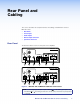
Rear Panel and Cabling This section describes the rear panel features and cabling of the MPA 401‑70V and MPA 401‑100V. • Rear Panel • Power Input • Audio Inputs • Remote Input Connector • Speaker Connections Rear Panel The illustration below shows the rear panel of the amplifiers: MPA 401-70V L POWER REMOTE (SUMMED) L (SUMMED) R 10V 70V OUTPUT 50mA R 12V 1.
Power Input a Power receptacle — A 36 W desktop power supply is provided. ATTENTION: When the PS 1230 power supply is connected to the MPA 401, it must not be shared with any other devices. MPA 401 series Amplifier PS 1230 Power Supply MPA 401 series Amplifier AC Power Cord POWER Smooth Power Receptacle DC Power Outputs 12V 1.5 A MAX A Ridges POWER A Power Supply Output Cord 12V 1.5 A MAX DO NOT USE DC Power Cord Captive Screw Connector Captive Screw Connector SECTION A–A 3/16" (5 mm) Max.
Audio Inputs Use the rear panel receptacles (see figure at right) to connect audio sources to the amplifier. Wire the connectors as shown below. The balloon numbers refer to the figure to the right. 3 L 2 (SUMMED) 4 L (SUMMED) R R NOTE: The ground pins of the input receptacles may be labeled or (see the images to the right). The wiring and function are the same whichever way the product is labeled.
Remote Input Port e Remote input port — This 3-pin, captive screw port allows a wall‑mounted audio controller to control volume and mute levels remotely (see Remote Control Options on page 12 if using a MediaLink controller). NOTE: The remote control port may be labeled in one of two ways (see the diagram to the right). The wiring and function are the same whichever way the product is labeled.
Controlling multiple amplifiers with one volume controller Several MPA 401 units can be daisy-chained so that one volume controller can simultaneously regulate the volume of all the amplifiers. NOTES: • As additional amplifiers are added to the daisy chain, the sensitivity of the volume potentiometer will change. The maximum volume level (fully clockwise) will not be affected.
Speaker Connections f Speaker receptacle (see figure 2) — Connect the speakers to the speaker receptacle using the 2-pole, 5 mm screw-lock captive screw connector (MPA 401-100V shown at right). 100V OUTPUT CLASS 2 WIRING OUTPUT 100V NOTES: RCA • The mono audio speaker receptacle may be labeled in one of two ways (see the diagrams above). The wiring and function are the same whichever way the product is labeled.
Setup and Operation This section provides information about the front panel features and operation of the MPA 401‑70V and MPA 401-100V: • Front Panel Features • Setting Input Level • Setting Bass and Treble • Remote Control Options • Troubleshooting Front Panel Features The front panels of the MPA 401‑70V and MPA 401‑100V are identical and shown below: 2 LEVEL BASS TREBLE 1 MPA 401 MINI POWER AMPLIFIER Figure 7.
Setting Input Level LEVEL BASS TREBLE Adjust the input level as follows: 1. If necessary, unplug the remote connector from the unit. MPA 401 MINI POWER AMPLIFIER 2. If connecting the amplifier to a system with adjustable volume, set the volume to its lowest point. Then adjust the level potentiometer fully counterclockwise to its minimum setting. 3. Set the system volume to its maximum level. No sound should come out. 4. Slowly increase the amplifier level until sound distortion starts to occur.
Remote Control Options Extron SI 3CT LP a Full-Range Ceiling Speakers Extron VCM 100 AAP Volume/Mute Controller TE MU ME LU VO AP M VC 0A b Extron 10 MLC 104 IP Plus Controller 1 G RIN WI ND S 2 OU AS GR T S! CL NOT OR UT SH TP DO OR OU R KE mA EA 50 TE E V MO UTA 50m 10RE L/M VO US TED O) ON (M LL L (SU Extron MPA 401 R R ED) ) ED MM O) 4 FIG CON 4 IP C 10 ML AS E 3 ME S2 R 2 F OF ON LU VO G V RIN 70WI 10V CL OT G M C RE V R ON (SU ER WER POW PO MM AY
Troubleshooting Under different circumstances, the front panel LED lights green or amber, which provides diagnostic information. Amplifier Fails to Exit Standby Mode Promptly Power LED Color Problem Description Problem Solution Amber No output signal. • No input detected: verify that there is an input signal. If a signal is present, raise the input level. • The amplifier is in standby mode and the output has been turned off. Check the remote port.
Reference Material This section of the user guide contains information about Mounting the MPA 401. Mounting Plenum Placement The MPA 401-70V and MPA 401-100V amplifiers meet UL 2043 requirements for heat and smoke release. They can be installed in the ceiling, out of sight, with reduced risk of theft. ATTENTION: Although the amplifier is plenum rated, the power supply provided with it is not. The power supply must not be placed in the plenum space.
ATTENTION: Use only the two holes indicated in figure 9 for mounting the MPA 401. The other four holes anchor stand-offs for the internal circuit boards; using them may damage the amplifier and will not provide secure mounting for the unit. #4-40 Thread Thru Rack Mounting 3.70" (9.39 cm) #4-40 Thread Thru Rack Mounting 4.44" (11.29 cm) Figure 9.
Extron Warranty Extron Electronics warrants this product against defects in materials and workmanship for a period of three years from the date of purchase.