User Guide Twisted Pair MTP AV Series Video and Audio Twisted Pair Transmitters and Receivers 68-732-01 Rev.
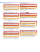
Safety Instructions • English WARNING: This symbol, , when used on the product, is intended to alert the user of the presence of uninsulated dangerous voltage within the product’s enclosure that may present a risk of electric shock. ATTENTION: This symbol, , when used on the product, is intended to alert the user of important operating and maintenance (servicing) instructions in the literature provided with the equipment.
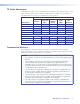
FCC Class A Notice This equipment has been tested and found to comply with the limits for a Class A digital device, pursuant to part 15 of the FCC rules. The Class A limits provide reasonable protection against harmful interference when the equipment is operated in a commercial environment. This equipment generates, uses, and can radiate radio frequency energy and, if not installed and used in accordance with the instruction manual, may cause harmful interference to radio communications.
Conventions Used in this Guide Notifications The following notifications are used in this guide: CAUTION: Electrical Shock that may result in injury. Use tools with care to prevent injury. ATTENTION: Attention indicates a situation that may damage or destroy the product or associated equipment. NOTE: A note draws attention to important information. TIP: A tip provides a suggestion to make working with the application easier.
Contents Introduction..................................................... 1 Reference Information.................................. 15 About the MTP Transmitters and Receivers......... 1 TP Cable Advantages.......................................... 2 Transmission Distance......................................... 2 Mounting Options.............................................. 15 UL Requirements........................................... 15 Tabletop Use (All Except AAP Models)...........
MTP AV Series • Contents v
Introduction This section introduces the MTP transmitters and receivers. Topics discussed in this section are: • About the MTP Transmitters and Receivers • TP Cable Advantages • Transmission Distance About the MTP Transmitters and Receivers The Extron MTP transmitters and receivers provide a system for long-distance distribution of NTSC, PAL, or SECAM video and audio.
TP Cable Advantages Twisted pair (TP) cable is much smaller, lighter, more flexible, and less expensive than coaxial cable. These TP products make cable runs simpler and less cumbersome. Termination of the cable with RJ-45 connectors is simple, quick, and economical.
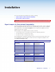
Installation This section describes the installation procedures, including: • Signal Jumpers for Generational Compatibility • Panel Features and Connections CAUTION: Installation and service must be performed by authorized personnel only. Signal Jumpers for Generational Compatibility Over time, the MTPs have been redesigned, affecting the signal content of the TP cable wire pairs, changing the audio from stereo to mono, and eliminating the remote power capability.
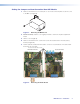
Setting the Jumpers on New Generation Non AAP Models Figure 1. SHARP GAIN 1. Remove and retain the four screws (two on each side of the unit) that secure the cover to the MTP (see figure 1). Removing the MTP Cover 2. For the receiver, slide the cover slightly forward to clear the front panel adjustment knobs. 3. Lift the cover straight up. 4. Remove and retain the two screws that secure the audio board to the main (video) board (see figure 2). 5.
6. Locate the jumper blocks (see figure 3) on the video board. Shift the jumper to the alternate location. Mono (default jumper position) Compatible with new model transmitter/receivers. Cannot remotely power transmitter/receiver. Transmitter Front Panel Transmitter Rear Panel Receiver Front Panel Receiver Rear Panel Stereo Compatible with old model transmitter/receivers. Can remotely power transmitter/receiver. Figure 3. Video Board Jumper Locations 7.
Setting the Jumpers on AAP Transmitters 1. Remove and retain the two screws that secure the back cover to the MTP (see figure 5). 1. Remove these Screws 2. Carefully pull the RJ-45 connector through this hole. OUTPUT − + POWER 12V 0.5A MAX Figure 5. Removing the MTP Cover 2. Pull the cover out of the way, carefully twisting the RJ-45 connector as necessary to slide it through the hole in the cover marked “Output.” 3.
Panel Features and Connections Transmitter Input Connections Figure 8 shows all of the combinations of video and audio input connectors that you may encounter with your MTP transmitter. INPUT L R L 3 12V 0.5a MAX S-VIDEO R 3 OUTPUT 12V 0.5a MAX MTP T SV A MTP T SV A, 1 Rear Panel OUTPUT VIDEO MTP T AV MTP T AV, Rear Panel 2 INPUT INPUT 4 4 L R 12V 0.5a MAX INPUT S-VIDEO L OUTPUT 12V 0.
CAUTIONS: • The length of the exposed (stripped) portion of the copper wires is important. The ideal length is 3/16 inches (5 mm). Longer bare wires can short together. Shorter bare wires are not as secure in the direct insertion connectors and could be pulled out. • The captive screw audio connector can easily be inadvertently plugged partially into one receptacle and partially into an adjacent receptacle. This misconnection could damage the audio output circuits.
Transmitter and Receiver Throughput Connections Figure 12 identifies the connections between the transmitter and receiver. INPUT L 12V 0.5a MAX OUTPUT R S-VIDEO L OUTPUT 12V 0.5a MAX MTP T SV A RCA R S-VIDEO INPUT MTP R SV A RCA 1 L 12V 0.5a MAX 1 INPUT R VIDEO L OUTPUT 12V 0.5a MAX MTP T AV MTP Transmitters OUTPUT INPUT R VIDEO MTP R AV MTP Receivers 1 OUTPUT − + POWER 12V 0.5A MAX Figure 12.
TP cable termination Figure 13 details the recommended termination of TP cables with RJ-45 connectors in accordance with the TIA/EIA T 568A or TIA/EIA T 568B wiring standards. You can use either standard, but ensure that you use the same standard on both cable ends. ATTENTION: cables.
Power Connection (All Models) See figure 14 to identify the power connections, indicators, and panel screws. 1 1 INPUT L OUTPUT R L 2 R 2 12V 0.5a MAX S-VIDEO OUTPUT 12V 0.5a MAX MTP T SV A RCA MTP Transmitters S-VIDEO INPUT MTP R SV A RCA MTP Receivers 2 OUTPUT − + POWER 12V 0.5A MAX MTP AAP Transmitters VIDEO IN R AUDIO IN L MTP T AV 1 Figure 14.
ATTENTION: • Power supply voltage polarity is critical. Incorrect voltage polarity can damage the power supply and the MTP. Identify the power cord negative lead by the ridges on the side of the cord (see figure 15). • The length of the exposed (stripped) copper wires is important. The ideal length is 3/16 inches (5 mm). Longer bare wires can short together. Shorter wires are not as secure in the captive screw connectors and could be pulled out.
c Captive screw audio connector (MTP R SV A, MTP R AV) — Connect a balanced or unbalanced audio device, such as an audio amplifier, to this 3.5 mm, 5-pole captive screw connector (see figure 17 to properly wire the output connector). No Ground Here R R Tip Sleeves Tip L L Tip Ring Sleeves Tip Ring Do not tin the wires! No Ground Here Balanced Audio Output Unbalanced Audio Output Figure 17. Captive Screw Connector Wiring for Audio Output ATTENTION: • Connect the sleeve to ground ( ).
Operation This section describes: • Front Panel Features • Troubleshooting — Skew Delay Compensation MTP R Composite Video Receiver Front Panel 3 3 2 SHARP 1 C GAIN 2 Y GAIN 3 SHARP 1 GAIN Front Panel Features MTP R S-video Receiver Front Panel Figure 18. MTP Receiver Front Panels a Power LED — When lit, this LED indicates power is applied to the MTP. b Sharpness — Adjusts the output image sharpness for long cable runs.
Reference Information This section provides information on: • Mounting Options Mounting Options NOTE: For rack, furniture, or projector mount installation, see the instructions provided with the kit. UL Requirements The following Underwriters Laboratories (UL) requirements pertain to the installation of the MTP transmitters or receivers in a rack. 1.
Frame Mounting (AAP Models) The MTP T AV AAP transmitters can be mounted to any Extron AAP mounting frame that accepts a double space (double height) AAP module (see “AAP Accessories” on page 15 for a partial list of AAP devices). NOTE: The rear panel MTP connections will be inaccessible after installation.
Extron Warranty Extron Electronics warrants this product against defects in materials and workmanship for a period of three years from the date of purchase.