User Guide Twisted Pair MTP T 15HD A Architectural Twisted Pair Transmitters MTP T 15HD WM, MTP T 15HD A D, MTP T 15HD A AAP 68-2207-01 Rev.
Safety Instructions Safety Instructions • English WARNING: This symbol, , when used on the product, is intended to alert the user of the presence of uninsulated dangerous voltage within the product’s enclosure that may present a risk of electric shock. ATTENTION: This symbol, , when used on the product, is intended to alert the user of important operating and maintenance (servicing) instructions in the literature provided with the equipment.
FCC Class A Notice This equipment has been tested and found to comply with the limits for a Class A digital device, pursuant to part 15 of the FCC rules. The Class A limits provide reasonable protection against harmful interference when the equipment is operated in a commercial environment. This equipment generates, uses, and can radiate radio frequency energy and, if not installed and used in accordance with the instruction manual, may cause harmful interference to radio communications.
Conventions Used in this Guide Notifications The following notifications are used in this guide: WARNING: A warning indicates a situation that has the potential to result in death or severe injury. ATTENTION: Attention indicates a situation that may damage or destroy the product or associated equipment. NOTE: A note draws attention to important information. Specifications Availability Product specifications are available on the Extron website, www.extron.com.
Contents Introduction .................................................... 1 Reference Information ................................ 15 About this Guide.................................................. 1 About the MTP Transmitters................................ 1 Twisted Pair Cable Advantages........................ 1 Transmission Distance..................................... 1 About the MTP T 15HD A WM ......................... 3 About the MTP T 15HD A D ............................
Introduction This section gives an overview of the user guide. This section also describes the MTP 15HD A Architectural Series of transmitters. Topics that are covered include: • About this Guide • About the MTP Transmitters About this Guide This guide contains installation, configuration, and operation information for the Extron MTP 15HD A Architectural Series of transmitters.
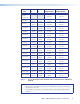
Video Format Pre-Peak Pre-Peak off on Composite, S-video, Component Max. Distance (High Quality) Max.
NOTES: • The transmitters are for use with, and perform best with Extron Enhanced Skew-Free AV cable terminated in accordance with the TIA/EIA T 568 A wiring standard. CAT 5 cables are acceptable but less preferable. We also recommend the use of pre-terminated and tested cables. Cables terminated on site should be tested before use to ensure that they comply with Category 5 specifications.
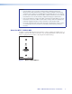
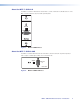
About the MTP T 15HD A D The MTP T 15HD A D Twisted Pair Transmitter is a wall or furniture mountable version of the MTP T 15HD A that fits any Decora® style wall plate. AUDIO IN COMPUTER IN Figure 3. MTP T 15HD A D Face About the MTP T 15HD A AAP The MTP T 15HD A AAP Twisted Pair Transmitter can be mounted in any Extron product that accepts a double space AAP, such as the AAP 102. AUDIO IN COMPUTER IN MTP T 15HD A Figure 4.
Installation This section provides information on: • Installing the MTP T 15HD A WM and MTP T 15HD A D • Installing the MTP T 15HD A AAP • Connections and Settings • Power Supply Wiring and Grounding • Twisted Pair Cable Termination • EDID Minder Configuration Installing the MTP T 15HD A WM and MTP T 15HD A D The MTP T 15HD A WM and MTP T 15HD A D can be installed in a one-gang electrical wall box, with the MTP T 15HD A D fitting into a Decora wall plate cover (supplied).
5. With the power supply disconnected, feed cables for the output devices through the opening and through the wall box punch-out holes, securing them with cable clamps to provide strain relief. 6. Trim back, insulate, or do both to exposed cable shields with heat shrink to reduce the chance of short circuits. a. To prevent short circuits, the outer foil shield can be cut back to the point where the cable exits the cable clamp. b.
Final Installation After testing and making any adjustments, turn off the power supply and carefully insert the wall box or mud ring into the opening. Attach it with nails or screws, leaving the front edge flush with the outer wall or furniture surface (see figure 6). NOTES: • If attaching the wall box to wood, use four #8 or #10 screws or 10-penny nails. A minimum of 0.5 inches (1.3 cm) of screw thread must penetrate the wood.
Installing the MTP T 15HD A AAP The MTP T 15HD A AAP must be attached to a device faceplate or AAP wall plate and cabled before the device or wall plate is pretested or installed in a wall or furniture. 1. Before attaching any cables, insert the standoffs of the MTP T 15HD A AAP through the holes in the faceplate or AAP wall plate of the device. 2. Using the provided #4-40 nuts and captive washers, secure the AAP to the faceplate or wall plate. 3. Repeat steps 1 and 2 to mount any other AAPs.
Connections and Settings ATTENTION: Potential damage to property. Do not connect these devices to a computer data or telecommunications network. Front Panel Features The front panel features are the same on all the MTP T 15HD A architectural models, as shown in figure 9. 1 AUDIO IN 2 COMPUTER IN 3 1 2 1 2 3 AUDIO IN COMPUTER IN 3 AUDIO IN COMPUTER IN MTP T 15HD A MTP T 15HD A MTP T 15HD A D Figure 9.
Rear Panel Features With the exceptions of d, e, and f on the MTP T 15HD A D, as noted in the figures and descriptions, the rear panel features are the same on all the MTP T 15HD A architectural models. 1 1 ON PREPEAK 2 Hz OFF 2 50 4 60 EDID SELECT 3 5 3 6 6 Figure 10. MTP T 15HD WM and AAP (Left) and MTP T 15HD A D (Right) Rear Panel Features a Output connector — Connect one end of a twisted pair cable to this RJ-45 female connector on the transmitter.
d Frequency Select switch — The Frequency select DIP switch sets the vertical frequency of the factory-installed EDID. 50 Hz or 60 Hz can be selected. e EDID Select rotary switch — This 16 position rotary switch is used to select which factory-installed EDID information will be used. Position 0 is not used. Positions 1 through F correspond to the EDID information in the table in figure 15 on page 14.
POWER 12V 0.5A MAX Smooth A Ridges Rear Panel A 3/16" (5 mm) MAX Tie Wrap SECTION A–A Ridges Power Supply Output Cord Earth Ground Figure 13. Power Connector Wiring and Grounding WARNING: Failure to follow these instructions may result in serious injury. The two power cord wires must be kept separate while the power supply is plugged in. Disconnect the power before wiring. NOTES: • Your transmitter and receiver pair may have shipped with a blue captive screw connector.
Twisted Pair Cable Termination Figure 14 details the recommended termination of twisted pair cables with RJ-45 connectors in accordance with the TIA/EIA T568A or TIA/EIA T568B wiring standards. You can use either standard with CAT 5, 5e, or 6 cable, but ensure that you use the same standard on both ends of the cable. Pins: 12345678 Pin Insert Twisted Pair Wires RJ-45 Connector TIA/EIA T 568 A Wire color TIA/EIA T 568 B Wire color Signal 1 White-green White-orange Red/V. sync + Red/V.
EDID Minder Configuration The MTP T 15HD A D unit supports emulation of factory-installed EDID information through EDID Minder. To use factory-installed EDID information: 1. If you have not already done so, connect the source device to the MTP 15HD transmitter. Do not power on the source device at this time. 2. Set the rear panel DIP switch (see d on page 11) to the required frequency (50 or 60 Hz).
Reference Information This section includes a template with cut-out dimensions for installation of the MTP T 15HD A WM or MTP T 15HD A D transmitter. Decora Template Dimensions Use the dimensions in the cut-out template in figure 16 as a guide for cutting a hole in a wall or furniture. NOTES: • The drawing is not full size or to scale. DO NOT scale up or print to use as a template. • Full size templates are available online at www.extron.com. 2.79" (7.09 cm) Top Panel 1.9" (4.83 cm) 4.50" (11.43 cm) 2.
Extron Warranty Extron Electronics warrants this product against defects in materials and workmanship for a period of three years from the date of purchase.