User Guide Twisted Pair MTP 15HD A Series High Resolution Video and Serial Link MTP Transmitters and Receivers 68-2206-01 Rev.
Safety Instructions Safety Instructions • English WARNING: This symbol, , when used on the product, is intended to alert the user of the presence of uninsulated dangerous voltage within the product’s enclosure that may present a risk of electric shock. ATTENTION: This symbol, , when used on the product, is intended to alert the user of important operating and maintenance (servicing) instructions in the literature provided with the equipment.
FCC Class A Notice This equipment has been tested and found to comply with the limits for a Class A digital device, pursuant to part 15 of the FCC rules. The Class A limits provide reasonable protection against harmful interference when the equipment is operated in a commercial environment. This equipment generates, uses, and can radiate radio frequency energy and, if not installed and used in accordance with the instruction manual, may cause harmful interference to radio communications.
Conventions Used in this Guide Notifications The following notifications are used in this guide: WARNING: A warning indicates a situation that has the potential to result in death or severe injury. ATTENTION: Attention indicates a situation that may damage or destroy the product or associated equipment. NOTE: A note draws attention to important information. Specifications Availability Product specifications are available on the Extron website, www.extron.com.
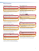
Contents Introduction............................................. 1 Mounting................................................ 19 About this Guide............................................... 1 About the MTP Transmitters and Receivers...... 2 Twisted Pair Cable Advantages..................... 2 Transmission Distance...................................... 3 Tabletop Placement........................................ 19 Under Desk and Furniture Mounting............... 19 Rack Mounting.......................
Introduction This section gives an overview of the user guide. This section also describes the MTP 15HD A Series of transmitters and receivers. Covered topics are: •• About this Guide •• About the MTP Transmitters and Receivers •• Transmission Distance About this Guide This guide contains installation, configuration, and operation information for two families of Extron MTP transmitters and receivers.
About the MTP Transmitters and Receivers The Extron MTP T 15HD A transmitter and MTP RL 15HD A and MTP RL 15HD A SEQ receivers are a system for long-distance distribution of VGA or other high resolution video and audio. The MTPs are a part of the Extron compact line of basic distribution amplifiers, switchers, transmitters and receivers, and associated video accessories. High resolution video on a 15-pin HD connector as well as stereo audio on a 3.5 mm stereo jack is sent to the MTP transmitter.
Transmission Distance The maximum distance is determined by the frequency and resolution of the signal that is input to the transmitter. The table on page 4 specifies the recommended maximum transmission distances and transmitter Pre-Peak switch positions (see figure 3, e on page 9) using Extron Enhanced Skew-Free AV UTP cable, STP201 cable, or CAT 5, 5e, 6, or 7 cable, terminated with RJ-45 connectors.
Video Format PrePeak off Pre-Peak on Composite, S-video, Component Max. distance (high quality) Max.
Installation and Operation This section provides information on: •• Installation Overview •• Front Panel Features •• Transmitter Rear Panel Features •• Receiver Rear Panel Features •• Power Supply Wiring and Grounding •• Twisted Pair Cable Termination •• Skew Delay Compensation •• EDID Configuration Installation Overview Follow the steps below to properly install and operate any of the Extron MTP 15HD A transmitters and receivers. ATTENTION: Potential damage to property.
Front Panel Features See figure 2 to identify the front panel features on the transmitter and receiver. MTP T 15HD A Transmitter EDID SELECT 50 Hz ON 1 RECORD 60 Hz 2 SPARE 4 3 MTP SERIES 5 H SYNC + V SYNC + S-VIDEO END UNIT SPARE MTP RL 15HD A Receiver RGB LEVEL PEAKING ON 1 1 2 3 4 5 MTP SERIES 6 11 7 DELAY RED SELECT 1 GREEN BLUE LEVEL RGB PEAKING H SYNC + V SYNC + S-VIDEO END UNIT SPARE MTP RL 15HD A SEQ Receiver ON ADJUST 1 2 3 4 5 MTP SERIES 8 Figure 2.
e EDID select rotary switch — The rotary switch is used to select specific pre-programmed or user-recorded EDID settings. Position 0 of this 16 position rotary switch is used to select the user recorded EDID. Position F passes the EDID from the display connected to the loop-out back to the input. Positions 1 through E select pre-programmed EDID resolutions. NOTE: The refresh rate of the pre-programmed EDID resolutions is selected using the first DIP switch (d).
k DIP switches (RL receivers only) — A 5-pole DIP switch is used to configure the features of the MTP receivers. •• Horizontal sync (H Sync +) switch — Set this switch On (up) for positive horizontal sync or Off (down) for negative sync. •• Vertical sync (V Sync +) switch — Set this switch On (up) for positive vertical sync or Off (down) for negative sync. NOTE: Most devices use negative sync for H Sync and V Sync.
Transmitter Rear Panel Features Figure 3 shows an MTP T 15HD A transmitter, which has all of the connectors and other features that are on either transmitter in the MTP 15HD A series. 4 MTP T 15HD A Transmitter MTP T 15HD A AUDIO PRE-PEAK POWER 12V .5A MAX ON INPUT 1 2 Figure 3. a NOTE: A “C7” label is affixed to transmitters designed for STP201 or CAT 7 cable.
d Audio input connector — Plug a 3.5 mm stereo audio plug into this connector for unbalanced audio input. Wire the plug as shown in figure 5. The stereo audio input is summed and output on the twisted pair cable as mono audio. Tip Left (+) Ring Right (-) Sleeve ( ) Figure 5. 3.
Receiver Rear Panel Features Figure 6 shows an MTP RL 15HD A receiver, which has all of the connectors and other features that are on either receiver in the MTP 15HD A series. NOTE: A “C7” label is affixed to transmitters designed for STP201 or CAT 7 cable. MT P RL 1 5 HD A POWER 12V .5A MAX INPUT OUTPUTS BUFFERED OUTPUT MONO AUDIO L R 5 RGB MTP RL 15HD A Receiver 1 2 Figure 6.
Power Supply Wiring and Grounding Figure 8 shows how to wire and ground the connector. ATTENTION: • Potential damage to property. Power supply voltage polarity is critical. Incorrect voltage polarity can damage the power supply and the transmitter or receiver. Identify the power cord negative lead by the ridges on the side of the cord. • To verify the polarity before connection, plug in the power supply with no load and check the output with a voltmeter.
ATTENTION: • Potential damage to property. This product is intended to be supplied by a Listed Power Unit marked "Class 2" or "LPS", rated 12 VDC, maximum 1.0 A. Always use a power supply supplied or specified by Extron. Use of an unauthorized power supply voids all regulatory compliance certification and may cause damage to the supply and the end product.
Twisted Pair Cable Termination Figure 9 details the recommended termination of twisted pair cables with RJ-45 connectors in accordance with the TIA/EIA T568A or TIA/EIA T568B wiring standards. You can use either standard with CAT 5, 5e, 6, 7, and STP201 cable, but ensure that you use the same standard on both ends of the cable. Pins: 12345678 Pin Insert Twisted Pair Wires RJ-45 Connector Figure 9. TIA/EIA T 568 A Wire color TIA/EIA T 568 B Wire color Signal 1 White-green White-orange Red/V.
Skew Delay Compensation CAT 5, 5e, 6, 7, and STP201 cable can lead to registration errors between the Red, Green, and Blue video signals. Pair skew can be measured with test equipment or identified by viewing a crosshatch test pattern with a critical eye to determine if either the Red, Green, or Blue video image leads (appears to the left of) the other two video images. NOTE: Unless the twisted pair cable is changed, the skew adjustment should need to be made only once, during installation.
EDID Configuration The MTP 15HD A transmitter can either record EDID from a display device, or a pre-programmed EDID can be selected using the rotary and DIP switches. Recording a Display EDID 1. Turn the rotary switch to position 0. NOTE: The vertical frequency DIP switch has no effect in this mode. 2. Connect the display device to the local monitor output connector. NOTE: The MTP 15HD transmitter should be supplying the necessary 5 VDC to power on the display.
Reference Information This section provides information about: •• Part Numbers, Optional Accessories, Cables, and Connectors Part Numbers, Optional Accessories, Cables, and Connectors Part Numbers MTP Transmitter and Receivers Part Number MTP T 15HD A transmitter 60-1282-01 or MTP RL 15HD A receiver 60-690-01 or MTP RL 15HD A SEQ receiver 60-690-02 Included Parts Part Number 12 VDC 1.
Cables NOTE: Extron Enhanced Skew-Free AV UTP cables are not recommended for Ethernet or LAN applications.
Mounting This section outlines the various mounting options available for the MTP 15HD A Series transmitters and receivers: •• Tabletop Placement •• Under-Desk Mounting •• Rack Mounting •• Projector Mounting Tabletop Placement Attach the four provided rubber feet to the bottom of the unit and place it in any convenient location. Under Desk and Furniture Mounting Mount the unit under a desk or podium using the optional Extron MBU 123 under desk mounting kit (part number 70‑212‑01).
Rack Mounting Procedure These units can be mounted on any of these optional rack systems, including: •• RSF 123: 3.5 inch deep, 1U rack shelf kit (part number 60-190-20) •• RSB 123: 3.5 inch deep, 1U basic rack shelf (part number 60-604-21) •• RSU 126: 6 inch deep, 1U rack shelf kit (part number 60-190-10) •• RSB 126: 6 inch deep, 1U basic rack shelf (part number 60-604-11) •• RSU 129: 9.5 inch deep, 1U rack shelf kit (part number 60-190-01) •• RSB 129: 9.
Extron Warranty Extron Electronics warrants this product against defects in materials and workmanship for a period of three years from the date of purchase.