User’s Manual MTP T 15HD A WM, MTP T 15HD A D, MTP T 15HD A AAP MTP T 15HD A Architectural Twisted Pair Transmitters 68-1241-01 Rev.
Precautions Safety Instructions • English This symbol is intended to alert the user of important operating and maintenance (servicing) instructions in the literature provided with the equipment. This symbol is intended to alert the user of the presence of uninsulated dangerous voltage within the product’s enclosure that may present a risk of electric shock. Caution Read Instructions • Read and understand all safety and operating instructions before using the equipment.
安全须知 • 中文 这个符号提示用户该设备用户手册中 有重要的操作和维护说明。 警告 电源 • 该 设 备 只 能 使 用 产 品 上 标 明 的 电 源 。 设 备 必须使用有地线的供电系统供电。 第三条线 (地线)是安全设施,不能不用或跳过。 这个符号警告用户该设备机壳内有暴 拔掉电源 • 为安全地从设备拔掉电源,请拔掉所有设备后 或桌面电源的电源线,或任何接到市电系统的电源线。 露的危险电压,有触电危险。 电源线保护 • 妥善布线, 避免被踩踏,或重物挤压。 注意 阅读说明书 • 用 户 使 用 该 设 备 前 必 须 阅 读 并 理 解所有安全和使用说明。 保存说明书 • 用户应保存安全说明书以备将来使 用。 遵守警告 • 用户应遵守产品和用户指南上的所有安 全和操作说明。 维护 • 所有维修必须由认证的维修人员进行。 设备内部没 有用户可以更换的零件。为避免出现触电危险不要自己 试图打开设备盖子维修该设备。 通风孔 • 有些设备机壳上有通风槽或孔,它们是用来防止 机内敏感元件过热。 不要用任何东西挡住通风孔。 锂电池 • 不正确的更换电池会有爆炸的危险。 必须使用与 厂家推荐的相同或相
Table of Contents About the MTP Transmitters ....................................................... 1 TP cable advantages ........................................................................... 1 Transmission distance ........................................................................ 1 About the MTP T 15HD A WM ........................................................... 4 About the MTP T 15HD A D ............................................................... 4 About the MTP T 15HD A AAP ........
Introduction About the MTP Transmitters The Extron MTP T 15HD A Architectural Twisted Pair Transmitters (available in either black or white) are a series of wall, Architectural Adapter Plate (AAP) or furniture mounting products that are based on the MTP T 15HD A Twisted Pair Transmitter. The Extron MTP T 15HD A architectural transmitters accept high resolution computer-video on a female 15-pin HD connector and a stereo audio signal on a female 3.5 mm mini stereo jack.
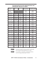
Recommended Pre-Peak switch positions and transmission distances at 60 Hz Video Format Pre-Peak off Pre-Peak on Composite, S-video, Component Max. distance (high quality) Max.
Introduction, cont'd 3 N The transmitters are for use with, and perform best with Extron Enhanced Skew-Free A/V cable terminated in accordance with the TIA/EIA T 568 A wiring standard. CAT 5 cables are acceptable but less preferable. We also recommend the use of pre-terminated and tested cables. Cables terminated on site should be tested before use to ensure that they comply with Category 5 specifications.
About the MTP T 15HD A WM The MTP T 15HD A WM Twisted Pair Transmitter is a wall or furniture mountable version of the MTP T 15HD A, and can be mounted into any standard one gang electrical wall box. AUDIO IN COMPUTER IN MTP T 15HD A Figure 1 — MTP T 15HD A WM face About the MTP T 15HD A D The MTP T 15HD A D Twisted Pair Transmitter is a wall or furniture mountable version of the MTP T 15HD A that fits any Decora® style wall plate.
Installation Installing the MTP T 15HD A WM and MTP T 15HD A D The MTP T 15HD A WM and MTP T 15HD A D can be installed in a one-gang electrical wall box, with the MTP T 15HD A D fitting into a Decora wall plate cover (supplied). If a suitable wall box is already installed, follow steps 5 through 8 below. To install a new wall box, follow all the steps below. Underwriters Laboratories (UL) Listed wall boxes are recommended.
Both braided and foil shields should be connected to an equipment ground at the other end of the cable. 7. Connect the output device cables to the rear of the MTP architectural wall plate. See "Rear panel features" on page 9 for connector wiring details. 8. Connect input devices (see "Front panel features" on page 8 for connector details), restore the power supply, and test the wall plate.
Installation, cont’d Wall Box Wall opening is flush with edge of box. IO D AU PC INP UT MTP T 15HD A D Decora Faceplate Figure 5 — Mounting the MTP T 15HD A D Installing the MTP T 15HD A AAP The MTP T 15HD A AAP must be attached to a device faceplate or AAP wall plate and cabled before the device or wall plate is pretested or installed in a wall or furniture. 1. Before attaching any cables, insert the MTP T 15HD A AAP’s standoffs through the holes in the device’s faceplate or AAP wall plate. 2.
Connections and Settings Do not connect these devices to a computer data or telecommunications network. C Front panel features The front panel features are the same on all the MTP T 15HD A architectural models, as shown in figure 7.
Installation, cont’d c Video input connector — Connect a computer video source to this 15-pin HD connector for high resolution video input. N 10 5 15 1 6 11 Female Input only sync signals (no video signals) on the sync pins, 13 and 14. For component video, use the R (R-Y) and R return pins (pins 1 and 6), G (Y) and G return pins (pins 2 and 7), and B (B-Y) and B return pins (pins 3 and 8). For S-video, use the R, R return (C-chroma), G, and G return (Y-luma) pins.
b Stereo Audio output connector — Insert bare wires into this direct insertion 3.5mm, 5-pole captive screw audio connector for stereo audio outputs. Wire the connector as shown in figure 10. Tip See Caution Sleeve (s) Tip See Caution Tip Ring Sleeve (s) Tip Ring L AUDIO R L AUDIO R The length of exposed wires is critical. The ideal length is 3/16" (5 mm). • If the stripped section of wire is longer than 3/16", the exposed wires may touch, causing a short circuit between them.
Installation, cont’d C N 11 The length of the exposed (stripped) copper wires is important. The ideal length is 3/16 inches (5 mm). Longer bare wires can short together. Shorter wires are not as secure in the direct insertion connectors and could be pulled out. Do not tin the power supply leads before installing in the direct insertion connector. Tinned wires are not as secure in the connectors and could be pulled out.
TP Cable Termination N RJ-45 termination with CAT 5, CAT 5e, or CAT 6 cable must comply with the TIA/EIA T 568A or TIA/EIA T 568B wiring standards for all connections. RJ-45 termination with Skew-Free A/V UTP cable must comply with TIA/EIA T 568 A only. Figure 12 details the recommended termination of TP cables with RJ-45 connectors in accordance with the TIA/EIA T 568A or TIA/EIA T 568B wiring standards.
Installation, cont’d Template The cut-out template, shown in figure 13, is used to install a MTP T 15 HD A WM or MTP T 15HD A D. Use the dimensions in the cut-out template as a guide for cutting a hole in a wall or furniture. N The drawing is not full size or to scale. Do not scale up or print to use as a template. Full size templates are available online at www.extron.com 2.79" (7.09 cm) Top Panel 1.9" (4.83 cm) 4.50" (11.43 cm) 2.8" (7.
Application Diagrams MTP R 15HD A Projector B ING RGPEAK LE L VE M TP SE R IE S Audio Enhanced Skew Free UTP Cable Laptop w/ Audio DIO AU UT PC INP M HD MTP AW 15 MTP 15HD A WM N This example application shows the MTP T 15HD WM, but also applies to the MTP T 15HD A D Figure 14 — Typical MTP T 15 HD A WM application MTP R 15HD A Projector B ING RGPEAK L VE LE M TP SE R IE S Laptop w/ Audio Enhanced Skew Free UTP Cable ER UT MP CO IN DIO AU IN PT 15 HD MTP T 15HD A AAP
Specifications Video Gain ������������������������������������������������� Unity Number/signal type ��������������������� 1 set of proprietary analog signals Connectors ������������������������������������� 1 female RJ-45 Video input and loop through Number/signal type ��������������������� 1 analog RGBHV, RGBS, RGsB, RsGsBs, component video, S-video, or composite video Connectors ������������������������������������� 1 female 15-pin HD Nominal level �������������������������������� 1 Vp-p for Y of compon
Audio input Number/signal type ��������������������� Connectors ������������������������������������� Impedance �������������������������������������� Nominal level �������������������������������� Maximum level ������������������������������ N 1 stereo, unbalanced 1 mini stereo jack, 3.5 mm >10k ohms, unbalanced +4 dBu (1.23 Vrms), -10 dBV (316 mVrms) +18 dBu, unbalanced at 1%THD+N 0 dBu = 0.
Part Numbers Enclosure ���������������������������� 2.7" H x 1.4" W x 1.4" D (6.9 cm H x 3.6 cm W x 3.6 cm D) Product weight ������������������������������ 0.4 lbs (0.2 kg) Shipping weight ���������������������������� WM model - 2.0 lbs (1 kg) AAP/D models - 2.
Optional Accessories Cables – various lengths Part number VGA with audio cables - male to male 26-490-xx *UTP23SF-4, non-plenum 26-569-xx *UTP23SF-4P, plenum 26-570-xx Cables – Bulk *UTP23SF-4/1000, non-plenum 22-141-03 *UTP23SF-4P/1000, plenum 22-142-03 * formerly known as Enhanced Skew-Free™ A/V UTP N Enhanced Skew-Free™ A/V UTP cables are not recommended for Ethernet/LAN applications. RJ-45 connector Part number CAT 6 jack (black), qty. 10 100-476-01 CAT 6 jack (red), qty.
Dimensions Dimensions The drawings in this section are not full size. Do not scale. N 2X EXTRUSION FOR #6-32 SCREW TAPPING 2.790 1.395 0.000 ø 0.156 THRU WITH ø 0.290 X 82° C'SINK (2 PLACES) 0.000 2.610 0.610 2.005 Ø.132 V THRU Ø.258 THRU AUDIO IN 1.545 ø 0.125 THRU 1.550 COMPUTER IN .984 ø 0.330 THRU WITH ø 0.562 C'BORE 0.070 DEEP AUDIO IN 2.010 COMPUTER IN 2.570 .000 MTP T 15HD A WM MTP T 15HD A D Ø.132 [Ø3.353] THRU Ø.258 [Ø6.553] THRU 4X R.050 [R1.270] [ +.000 1.390 -.015 35.
Extron Warranty Extron Electronics warrants this product against defects in materials and workmanship for a period of three years from the date of purchase.
Extron USA - West Headquarters +800.633.9876 Inside USA / Canada Only +1.714.491.1500 +1.714.491.1517 FAX Extron USA - East Extron Europe Extron Asia Extron Japan Extron China Extron Middle East +800.633.9876 +800.3987.6673 +800.7339.8766 +81.3.3511.7655 +81.3.3511.7656 FAX +400.883.1568 +971.4.2991800 +971.4.2991880 FAX +1.919.863.1794 +1.919.863.1797 FAX +31.33.453.4040 +31.33.453.4050 FAX +65.6383.4400 +65.6383.