Setup Guide Twisted Pair MTPX Plus 6400 Series MTP Twisted Pair Matrix Switchers Extron USA - West Headquarters +800.633.9876 Inside USA and Canada Only Extron USA - East Extron Europe Extron Asia Extron Japan +800.633.9876 Inside USA and Canada Only +800.3987.6673 Inside Europe Only +800.7339.8766 Inside Asia Only +81.3.3511.7655 +400.883.1568 +81.3.3511.7656 FAX Inside China Only +31.33.453.4040 +65.6383.4400 +1.919.863.1794 +31.33.453.4050 FAX +65.6383.4664 FAX +1.714.491.1500 +1.919.863.
Precautions Safety Instructions • English This symbol is intended to alert the user of important operating and maintenance (servicing) instructions in the literature provided with the equipment. This symbol is intended to alert the user of the presence of uninsulated dangerous voltage within the product’s enclosure that may present a risk of electric shock. Caution Read Instructions • Read and understand all safety and operating instructions before using the equipment.
安全须知 • 中文 警告 这个符号提示用户该设备用户手册中 有重要的操作和维护说明。 电源 • 该 设 备 只 能 使 用 产 品 上 标 明 的 电 源 。 设 备 必须使用有地线的供电系统供电。 第三条线 (地线)是安全设施,不能不用或跳过。 这个符号警告用户该设备机壳内有暴 拔掉电源 • 为安全地从设备拔掉电源,请拔掉所有设备后 或桌面电源的电源线,或任何接到市电系统的电源线。 露的危险电压,有触电危险。 电源线保护 • 妥善布线, 避免被踩踏,或重物挤压。 注意 阅读说明书 • 用 户 使 用 该 设 备 前 必 须 阅 读 并 理 解所有安全和使用说明。 保存说明书 • 用户应保存安全说明书以备将来使 用。 遵守警告 • 用户应遵守产品和用户指南上的所有安 全和操作说明。 维护 • 所有维修必须由认证的维修人员进行。 设备内部 没有用户可以更换的零件。为避免出现触电危险不要自 己试图打开设备盖子维修该设备。 通风孔 • 有些设备机壳上有通风槽或孔,它们是用来防止 机内敏感元件过热。 不要用任何东西挡住通风孔。 锂电池 • 不正确的更换电池会有爆炸的危险。 必须使用 与厂家推荐的相同
Contents Introduction ........................................1 About this Guide .................................1 About the MTPX Plus Matrix Switchers ...............................2 Twisted Pair (TP) Cable Transmission Distance .......................4 TP Skew Equalization ..........................6 Installation ..........................................7 Rear Panel ............................................7 Inputs ...............................................8 RS-232 output inserts .............
Introduction This section gives an overview of the Extron® MTPX Plus 6400 Series and describes their features. Topics that are covered include: • About this Guide • About the MTPX Plus Matrix Switchers • Twisted Pair (TP) Cable Transmission Distance • TP Skew Equalization About this Guide NOTE: For more information on any subject in this guide, see the MTPX Plus 6400 Series User Guide, available on the Extron DVD or at www.extron.com.
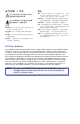
About the MTPX Plus Matrix Switchers The MTPX Plus matrix switchers (see figure 1) distribute signals that are compatible with the Extron MTP and VTT/VTR product lines. The matrix switcher routes a TP input signal to any combination of TP outputs. Depending on the MTP model, the routed TP signal can include RGB or low resolution video and either mono audio or transmitter-to-receiver RS-232 serial communications. The matrix switcher can route multiple input/output configurations simultaneously.
Twisted Pair (TP) Cable Transmission Distance CAUTION: NOTES: • The minimum TP cable length should be 25 feet (7.6 m). Do not connect this device to a computer data or telecommunications network. The maximum distance is determined by the frequency and resolution of the signal that is input to the transmitter or to one of the local inputs of the matrix switcher.
TP Skew Equalization Skew exists between wire pairs when the physical length of one wire pair is different from another. Skew affects the displayed image when the difference in length between wire pairs exceeds 2 feet. The difference in length causes the timing of the red, green, and blue video signals to appear out of alignment (horizontal registration errors). The signals transmitted on the shortest pair are shifted to the left if you are using white lines on a black background.
NOTE: RS-232 Output Inserts The other MTPX Plus matrix sizes are housed in the same 10U enclosure as the MTPX Plus 6464, but have fewer connectors to accommodate their smaller matrix sizes. CAUTION: e RS-232 Output Insert connectors — For bidirectional RS-232 data that is routed to a specific (unswitchable) TP output, connect a serial device to one of the RS-232 Output Insert 3-pole captive screw connectors.
Power and Fans h Local audio outputs — Connect audio devices, such as audio amplifiers or powered speakers to these 3.5 mm, Mono Audio (local audio) Outputs 5-pole captive screw connectors to receive unamplified, mono line level audio. NO GROUND HERE. Unbalanced Stereo Output Figure 5. Audio Output Connector Wiring CAUTION: NOTE: Tip Ring Sleeve(s) Tip Ring R Do not tin the wires! Sleeve(s) Tip sources. L Tip NO GROUND HERE.
Front Panel Operations Front Panel I/O VIDEO CONFIG AUDIO POWER SUPPLY PRIMARY 1 2 REDUNDANT 1 2 MTPX PLUS SERIES MTP MATRIX SWITCHER This section describes simple MTPX Plus matrix switcher operation from the front panel.
4. Press and release the desired output buttons. Amber indicates video and audio tie. Green indicates video only tie. Red indicates audio only tie. 3 4 8 The matrix switcher has three levels of front panel security lock that limit the operation of the switcher from the front panel. The three levels are: ENTER Green indicates the need to confirm the change. 5. Press and release the Enter button. All button indicators turn off.
Selecting Lock Mode 2 or Toggling Between Mode 2 and Mode 1 NOTES: • If the switcher is in Lock mode 0 or mode 1, this procedure selects mode 2. Defining the Audio/RS-232 Wire Pair and Configuring the Remote Port 1. To enter Configuration mode, simultaneously press and hold the Enter, Preset, View, and Esc buttons. Press and hold the Control buttons. • If the switcher in in Lock mode 2, this procedure selects mode 1.
3. To change the audio/RS-232 wire pair configuration of an input, press and release the input button to toggle the configuration for that input. Press Viewing Ties (and Muting Outputs) 1. Press the View button. Output buttons light for outputs that have no ties established. NOTE: 1 2 3 Input button toggles: Unlit --> red OR red --> unlit NOTE: 2. Press an input button. The buttons for all tied outputs light. 3. Press an output button. The buttons for the tied input and all tied outputs light.
Remote Control and Optimizing the Video This section describes using the remote control features of the MTPX Plus matrix switchers to control the devices. Topics that are covered include: • Selected SIS Commands • Installing and Starting the Control Program • Optimizing the Video • Accessing the HTML Pages Selected SIS Commands You can use Simple Instruction Set (SIS) commands for operation and configuration of the switchers.
Connection timeouts The Ethernet link times out and disconnects after a designated period of time of no communications. By default, this timeout value is set to 5 minutes but the value can be changed (see the "Configure port timeout SIS command" on page 33). NOTE: Extron recommends leaving the default timeout at 5 minutes and periodically issuing the Query (Q) command to keep the connection active or disconnecting the socket and reopening the connection when necessary.
24 Command/Response Table for SIS Commands MTPX Plus 6400 • Remote Control and Optimizing the Video Command ASCII Command Response (Host to Unit) (Unit to Host) Additional Description Create ties NOTES: • Commands can be entered back-to-back in a string, with no spaces. For example: 1*1!02*02&003*003%4*24$. • The matrix switchers support 1-, 2-, and 3-digit numeric entries (1*1!, 02*02&, or 003*003%). • The & tie command for RGB and the % tie command for video can be used interchangeably.
26 Command MTPX Plus 6400 • Remote Control and Optimizing the Video ASCII Command Response (Host to Unit) (Unit to Host) Input signal level and peaking and auto calibrate Set input signal level EX!*X^Ipek} Increment input peaking Decrement input peaking Read input peaking setting Execute auto calibration EX!+Ipek} EX!–Ipek} EX!Ipek} EX!*0AADJ} Additional Description IpekX!*X^] Set a specific pre-peak level for the TP input. IpekX!*X^] Increase the input pre-peaking level by 1.
28 Command MTPX Plus 6400 • Remote Control and Optimizing the Video Output skew adjustment Set all output skew adjustment values Example: Increment one output skew adjustment value Example: Decrement one output skew adjustment value Read output skew adjustment values Output pre-peaking Set output pre-peaking on Set output pre-peaking off Read output pre-peaking setting ASCII Command Response (Host to Unit) (Unit to Host) EX@*X**X**X*Oseq} OseqX@*X*red*X*green*X*blue] E2*0*0*4Oseq} EX@*X(+Oseq} Os
30 Command MTPX Plus 6400 • Remote Control and Optimizing the Video ASCII Command Response (Host to Unit) (Unit to Host) Additional Description Audio input gain and attenuation NOTE: The set gain (G) and set attenuation (g) commands are case sensitive. Set input audio gain to +dB value Example: X!*X1^G InX!•AudX1&] 1*2G In01•Aud+02] Set input audio attenuation to -dB value Increment gain X!*X1*g InX!•AudX1&] X!+G InX!•AudX1&] Increase gain by 1 dB.
32 Command MTPX Plus 6400 • Remote Control and Optimizing the Video ASCII Command Response (Host to Unit) (Unit to Host) Additional Description Lock (Executive) modes NOTE: See "Setting the front panel locks (executive modes)" on page 15 for more information on the Lock modes. Lock all front panel functions 1X Exe1] Enable Lock mode 1. Lock advanced front panel functions Unlock all front panel functions View lock status 2X Exe2] Enable Lock mode 2. 0X Exe0] Enable Lock mode 0.
Installing and Starting the Control Program Another way to operate the switcher is via the Windows®-based Matrix Switchers Control Program. This program is contained on the Extron Software Products DVD (included with the switcher). Run this program on a PC connected to a serial port (item i on page 10), Ethernet port (item j on page 10), or USB port (item o on page 12) on the switcher. The program must be installed on a Windows-based computer and cannot be run from the DVD.
3. Click Finish to exit the wizard. NOTE: You may need to repeat these steps if you subsequently connect the switcher to a different USB port on the same computer. Starting the Program 1. Click Start > Programs > Extron Electronics > Matrix Switchers > MATRIX Switcher + Control Pgm. The Comm Port Selection window appears. a. Examine the Matrix IP Address field, which displays the last Matrix IP address entered. If necessary, enter the correct IP address in the field. NOTE: 192.168.254.
Setting MTPX level and peaking using the MTP signal generator The simplest and surest way to set the input level and peaking is to use the included MTP signal generator and the Auto-calibration utility within the Matrix Switchers Control Program as follows: NOTE: To manually set the input level and peaking, see "Manually setting the MTPX level and peaking." 1. Disconnect the power and RJ-45 cables at the MTP transmitter that is connected to the MTPX Plus input to be adjusted. 2.
NOTES: • When the skew adjustment is set to zero, the MTPX Plus cannot shift the rightmost video image to the left. Selecting MTPX Plus Pre-Peak NOTE: If the cable between the MTPX Plus and the receiver is 300 feet (91 m) or longer, turn the Pre-Peak feature on the MTPX Plus on. For shorter cables, turn the feature off. • A 2-nanosecond adjustment is very fine. Up to 10 nanoseconds of delay may be necessary before you detect a change in the display. 7.
Accessing the HTML Pages NOTE: Another way to configure and operate the switcher is via its factoryinstalled HTML pages, which are always available and cannot be erased or overwritten. The HTML pages that are pre-loaded on the switcher are accessible through its LAN port, connected via a LAN or WAN, using a web browser such as Microsoft® Internet Explorer® (see item j on page 10, for connection information).
4. Press the keyboard key. The switcher checks whether it is password-protected. 6. The switcher downloads the HTML start-up page. The switcher is ready for operation via HTML remote control. If the switcher is not password-protected, it checks and downloads the HTML start-up page. The switcher is ready for operation via HTML remote control. If the switcher is password-protected, it downloads the Enter Network Password page. NOTE: A User name entry is not required. 5.
Maintenance and Modifications This section describes repairing the MTPX Plus 6400 matrix switchers by replacing power supplies and fans: • Removing and Installing a Power Supply Module • Removing and Installing a Fan Removing and Installing a Power Supply Module The MTPX Plus 6400 switchers have four power supply modules. The modules are identical. Each power supply module has a 2-color LED, visible on the rear panel, that indicates the status of the power supply outputs.
54 42 4 20 R L Rx Rx L TS Tx SE LY Rx 7 Tx L RS -232 Rx 8 Tx Rx Tx 63 25 51 R Tx MB 62 12 38 6 13 39 6 AS 61 11 24 50 L TP UT L INSE 9 14 40 27 53 8 L 43 R 12 Tx 44 R 57 L 13 Rx 15 16 Tx 46 MON 4 O 59 DIO 47 AU R Rx OU L 60 UT S 48 TP 5 Rx 61 R Tx 32 58 L Rx Tx 45 3 R 14 Tx 31 2 Rx Tx 30 56 L Rx 29 55 1 11 Tx 16 42 N Rx 28 54 IO 10 Tx 15 41 R RT 64 26 52 7 R OU Rx 48 10 37 R 5 Rx 47 60 23 49 5 Rx