User Guide Twisted Pair MTPX Plus 6400 Series MTP Twisted Pair Matrix Switchers 68-2020-01 Rev.
Safety Instructions • English Warning This symbol is intended to alert the user of important operating and maintenance (servicing) instructions in the literature provided with the equipment. Power sources • This equipment should be operated only from the power source indicated on the product. This equipment is intended to be used with a main power system with a grounded (neutral) conductor. The third (grounding) pin is a safety feature, do not attempt to bypass or disable it.
FCC Class A Notice This equipment has been tested and found to comply with the limits for a Class A digital device, pursuant to part 15 of the FCC Rules. Operation is subject to the following two conditions: 1. This device may not cause harmful interference. 2. This device must accept any interference received, including interference that may cause undesired operation.
Conventions Used in this Guide In this user guide, the following are used: NOTE: A note draws attention to important information. TIP: A tip provides a suggestion to make working with the application easier. CAUTION: WARNING: A caution indicates a potential hazard to equipment or data. A warning warns of things or actions that might cause injury, death, or other severe consequences.
Contents Introduction............................................................ 1 About this Guide................................................. 1 About the Matrix Switchers.................................. 1 TP Cable Advantages....................................... 4 Features............................................................... 8 Installation............................................................. 11 Setup and Installation Checklist.......................... 11 Get Ready.............
Matrix Software................................................... 86 Maintenance and Modifications..................... 140 Matrix Switchers Control Program...................... 86 Installing the Software................................... 87 Software Operation via Ethernet.................... 88 Using the Matrix Switcher Control Software... 89 IP Settings/Options Window........................... 94 Updating Firmware........................................ 99 Uploading HTML Files.......................
Introduction This section introduces the Extron MTPX Plus 6400 Series MTP Twisted Pair Matrix Switchers, including: zz About this Guide zz About the Matrix Switchers zz Features About this Guide NOTE: Throughout this guide all models are referred to as "MTPX Plus matrix switchers" unless a significant difference is noted in their input and output matrix size.
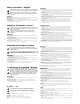
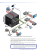
TouchLink™ VCR Control System DVD DOC CAM OP LAPT PC ON OFF Rack Mounted PC AY DISPL MUTE EN SCRE UP EN SCRE DOWN TCP/IP Switcher/Display Control ® LINK 3 ACT 1 3 1 RX TX 250 4 3 2 1 4 2 1 2 R 100 Y RELA T INPU IR COM IPL 4 2 3 Display Control Extron MTP U R RSA SEQ Universal Receiver -232 RS E AC SP TS Tx PU OUT Rx O O DI AU 2 MON 1 VID Y B- C Y/ Y Y R- RS 232 B RG WER POV 12 MAX .
The matrix switcher can be remotely controlled via its rear panel Remote (RS-232/RS-422) port and its front panel Configuration (USB) port using either the Extron Matrix Switchers Control Program or the Simple Instruction Set (SIS™). The SIS is a set of basic ASCII code commands that provides control through a control system or PC.
TP Cable Advantages Twisted pair cable is much smaller, lighter, more flexible, and less expensive than coaxial cable. These TP products make cable runs simpler and less cumbersome. Termination of the cable with RJ-45 connectors is simple, quick, and economical. CAUTION: Do not connect this device to a computer data or telecommunications network.
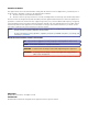
Table 1. Recommended maximum TP transmission distances at 60 Hz for configurations M TP T 1 5 H D A AUDIO PRE-PEAK POWER 12V .
Table 2. Recommended maximum TP transmission distances at 60 Hz — transmitter to receiver using MTPX Plus TP inputs and outputs MTP Transmitter MT P T 1 5 HD A AUDIO 3 PRE-PEAK POWER 12V .5A MAX ON INPUT MONITOR OFF OUTPUT MTPX Plus MTP Receiver OUTPUTS M TP U R A POWER VID 12V 0.
Table 3.
The MTPX Plus has a skew equalizer function that is available using SIS, the Windows-based control program, or built-in HTML page control. The skew function provides separate time delay circuits on the red, green, and blue video lines on the inputs and the outputs. Each time delay circuit can be independently adjusted, from 0 to 62 nanoseconds, to properly align the red, green, and blue video signals on the displayed image.
Operational reliability — The MTPX Plus matrix switcher can support round-the-clock operation in mission-critical applications, through the use of redundant power supplies and modular fans. zz Primary and redundant, hot-swappable power supplies — The hot-swappable, redundant power supplies are configured to automatically take over the load from the primary supplies in the case of a failure.
EDID Minder — Captures and stored EDID information, continuously making it available to all local inputs. EDID minder has two operating modes: zz Automatic (default) — Captures EDID for displays connected to the local outputs and provides data to the appropriate local inputs. zz User Assigned Mode — Rates from EDID table can be selected and assigned to any input. EDID file for the display connected to output 1 can be stored in the EDID table (four user-assigned locations are available).
Installation This section details the installation of the MTPX Plus matrix switchers, including: zz Setup and Installation Checklist zz Rear Panel Cabling and Features zz Front Panel Features Setup and Installation Checklist Get Ready c Familiarize yourself with the matrix switcher. c Obtain IP setting information for the matrix switcher from the local network administrator. Read “Ethernet Connection.” Perform Physical Installation c If desired, install the switcher in a rack (see page 140).
Rear Panel Cabling and Features 3 2 4 1 LOCAL INPUTS 1 INPUTS 2 INPUT SELECT LOCAL 1234 FAN ASSEMBLY 3 4 1 2 3 4 5 6 7 8 9 10 11 12 13 14 15 16 17 18 19 20 21 22 23 24 25 26 27 28 29 30 31 32 33 34 35 36 37 38 39 40 41 42 43 44 45 46 47 48 49 50 51 52 53 54 55 56 57 58 59 60 61 62 63 64 RJ-45 5 6 7 8 INPUT SELECT LOCAL 5678 RJ-45 7 LOCAL OUTPUTS 1 2 3 4 OUTPUTS 1 2 3 4 5 6 7 8 9 10 11 12 13 14 15 16 17 1
CAUTIONS: • Use electrostatic discharge (ESD) precautions (be electrically grounded) when making connections. Electrostatic discharge can damage equipment, even if you cannot feel, see, or hear it. • Remove system power before making all connections. Signal Inputs a Inputs (TP) connectors — Connect the TP outputs of compatible MTP or VTT transmitters to these RJ-45 female connectors. CAUTION: Do not connect this device to a computer data or telecommunications network.
NOTES: Enhanced Skew-free A/V cable is not recommended for Ethernet/LAN applications. This cable is specially designed for compatibility with the Extron twisted pair products that are wired using the TIA/EIA 568A standard. • The green, brown, and blue pairs of this cable have virtually identical lengths and should be used to transmit the RGB signals. • The orange pair of this cable has a different length and should not be used to transmit the RGB signals.
NOTES: • The length of exposed wires is critical. The ideal length is 3/16 inch (5 mm). zz If the stripped section of wire is longer than 3/16 inch, the exposed wires may touch, causing a short circuit. zz If the stripped section of wire is shorter than 3/16 inch, wires can be easily pulled out even if tightly fastened by the captive screws. • Figure 7 identifies the tip, ring, and sleeve. A mono audio connector consists of the tip and sleeve.
NOTES: • When an RS-232 output insert is enabled, any content on the audio/RS-232 wire pair for the TP input tied to that output is disabled. • The length of exposed wires is critical. The ideal length is 3/16 inch (5 mm) (see the audio input connector NOTES for more information). • The switch time for the RS-232 output insert is 50 ms. Signal Outputs f Outputs (TP) connectors — Connect the TP inputs of compatible MTP or VTR receivers to these RJ-45 female connectors.
NOTE: The length of exposed wires is critical. The ideal length is 3/16 inch (5 mm) (see the audio input connector NOTES for more information). These outputs are always outputs 1 through 8, with the same inputs tied to them as to TP outputs 1 through 8. NOTES: • The audio that is output on these connectors is converted from the tied proprietary TP input signal or the local audio input. This feature allows you duplicates of the outputs while eliminating the need for extra receivers.
Ethernet Connection j LAN port — For IP control of the system, connect the matrix switcher to a PC or to an Ethernet LAN via this RJ-45 connector. You can use a PC to control the networked switcher with SIS commands from anywhere in the world. You can also control the switcher from a PC that is running the Extron Matrix Activity Link Switchers Control Program or has downloaded HTML pages from the LED LED switcher.
Reset Button and LED k Reset button and LED — The recessed Reset button initiates four levels of matrix switcher reset. For four different reset levels, press and hold the button while the switcher is running or while you power up the switcher. RESET See “Rear Panel Operations” in the Operation section for details. zz Events (mode 3) reset — Toggles event monitoring on and off. zz IP settings (mode 4) reset — Reset the IP functions of the switcher.
Front Panel Features CONFIG POWER SUPPLY PRIMARY 1 2 REDUNDANT 1 2 MTPX PLUS SERIES MTP MATRIX SWITCHER 15 Figure 12. Front Panel Configuration Port o Configuration port — This mini USB B port provides a communications function similar to the rear panel Remote port, but it is easier to access than the rear port after the matrix switcher has been installed and cabled. A standard USB cable, available locally, can be used for this connection.
Operation This section describes the front panel operation of the MTPX Plus 6400 Series Matrix Switchers, including: zz Front Panel Controls and Indicators zz Rear Panel Power Indicators zz Front Panel Operations zz Rear Panel Operations zz Optimizing the Audio zz Video Adjustments zz Troubleshooting zz Configuration Worksheets Front Panel Controls and Indicators The front panel controls (see figure 13) are grouped into two sets.
NOTE: On switchers with smaller matrix sizes, the larger-numbered buttons are not used for input and output selection, although they are used to select and indicate preset numbers, indicate the input audio level, and indicate the output audio volume. The illuminated pushbuttons can be labeled with either text or graphics. The buttons can be set to provide amber background illumination all the time or the background illumination can be turned off (see “Background Illumination”).
a Input buttons — The input buttons have one primary function (❏) and six secondary functions (•): ❏ Select and identify an input. b zz (Input 1 only) With the Output 1 button, select I/O Group mode. zz Assign an input to the selected group in I/O Group mode and indicate its assignment. zz Select a preset. zz Display the output volume level. zz Select and identify the audio/RS-232 wire pair as audio (unlit) or RS-232 (lit) in Serial Port and Audio and RS-232 Input Configuration mode.
Control Buttons NOTE: See “Front Panel Operations,” later in this chapter for detailed descriptions of all of the following functions and operations. Primary functions Save changes. Select Preset mode. Select View mode. Cancel/escape. Blink: save needed Blink: Save preset Lit: Recall preset View mode selected Flashes once ENTER PRESET VIEW ESC Select group 1. Lit: group selected. Select group 2. Lit: group selected. Select group 3. Lit: group selected. Select group 4. Lit: group selected.
d Preset button — The Preset button has two primary functions (❏) and three secondary functions (•): ❏ Activates Save Preset mode to save a configuration as a preset and Recall Preset mode to activate a previously-defined preset. ❏ Blinks when Save Preset mode is active and lights steadily when Recall Preset mode is active. e zz In the I/O Group mode, selects group 2 and indicates the selection.
I/O Buttons NOTE: See “Front Panel Operations,” later in this chapter for detailed descriptions of all of the following functions and operations. Primary functions Action Indication Select video. Select audio. Green when selected Red when selected VIDEO AUDIO Secondary functions Front panel locks Resets Action 1: With Enter, select Lock mode 2 or toggle between mode 0 and mode 2. Action 2: Select Lock mode 1 or toggle between mode 2 and mode 1.
Power Indicators i Primary and Redundant Power Supply LEDs — POWER SUPPLY Green — Indicates that the associated power supply is operating within normal tolerances. PRIMARY 1 2 REDUNDANT 1 2 Red — Indicates that the associated power supply is operating outside the normal tolerances or has failed (see the “Maintenance and Modifications“ section to replace the power supply). Unlit — No power supply is installed.
Front Panel Operations The following paragraphs detail the power-up process and provide sample procedures for the following actions: zz Creating ties, sets of ties, and configurations zz Changing a configuration zz Viewing ties, sets of ties, and configurations zz Creating I/O groups zz Saving a preset zz Recalling a preset zz Muting and unmuting outputs zz Viewing and adjusting the input audio level zz Viewing and adjusting the local output volume zz Locking and unlocking the front panel
Power Apply power by connecting one or both power cords between the Primary and Redundant AC power connectors and the AC sources. The switcher performs a self-test that flashes the front panel buttons in a variety of patterns; then flashes all buttons green, red, and amber; and then turns them either off or to background illumination. An error-free power up selftest sequence leaves all control buttons either unlit or showing background illumination.
Creating a Configuration The current configuration can be changed using the front panel buttons. Change the current configuration as follows: 1. Press the Esc button to clear any front panel button indications that may be lit. 2. Select video, audio, or both for configuration by pressing the Video button and Audio button as necessary. 3. Select the desired input and outputs by pressing the input and output buttons.
Example 1: Creating a set of video and audio ties In the following example, input 5 is tied to outputs 3, 4, and 8. The steps show the front panel indications that result from your action. NOTE: This example assumes that there are no ties in the current configuration. 1. Clear all selections: Press and release the Esc button. Press the Esc button to clear all selections. C O NT R O L ENTER PRESET VIEW The button flashes once. ESC 2.
The current configuration is now input 5 tied to output 3, output 4, and output 8. Input 5 (video/audio) tied to outputs 3, 4, and 8 Input 5 3 4 Output 8 Video Audio Example 2: Adding a video tie to a set of video and audio ties In the following example, a new tie is added to the current configuration. The steps show the front panel indications that result from your action. NOTE: This example assumes that you have performed example 1. 1. Clear all selections: Press and release the Esc button.
The current configuration is now: zz Video — Input 5 is tied to output 1, output 3, output 4, and output 8. zz Audio — Input 5 is tied to output 3, output 4, and output 8. Input 5 video tied to outputs 1, 3, 4, and 8 Input 5 audio tied to outputs 3, 4, and 8 Input 5 1 3 4 Output 8 Video Audio Example 3: Removing an audio tie from a set of video and audio ties In the following example, an existing tie is removed from the current configuration.
5. Confirm the change: Press and release the Enter button. Press the Enter button to confirm the configuration change. All input buttons and output buttons return to unlit or background illumination. ENTER The Enter button returns to unlit or background illumination. The current configuration is now: zz Video — Input 5 video is tied to output 1, output 3, output 4, and output 8. zz Audio — Input 5 audio is tied to output 3 and output 8.
Viewing a Configuration The current configuration can be viewed using the front panel buttons. The View mode prevents inadvertent changes to the current configuration. View mode also provides a way to mute audio or RS-232 outputs (see “Muting and Unmuting Outputs”). View the current configuration as follows: 1. Press the Esc button to clear any front panel button indications that may be lit. 2. Press and release the View button.
3. Select video and audio for the tie: Press and release the Video button and the Audio button as necessary to light both. Press the Video button to toggle on and off. The button lights green when selected. I/O VIDEO AUDIO Press the Audio button to toggle on and off. The button lights red when selected.
6. Toggle the video and audio selection: Press and release the Video button and the Audio button. Press button. Press the button. I/O The button lights green when selected. VIDEO The button is unlit or background illuminated when deselected. AUDIO The buttons for outputs that are tied to Input 5 light green to indicate video ties (audio breakaway).
I/O Grouping I/O grouping is a matrix switcher feature that allows you to subdivide the front panel controls of the matrix into up to four smaller functional subswitchers (see figure 16) and limit tie creation using the front panel only. The I/O group limitation applies to tie creation from the front panel only. Inputs and outputs can be assigned to one of four groups or not assigned to any group. NOTE: All of the equipment in this figure is connected through the appropriate MTP transmitter or receiver.
Create I/O groups on the front panel as follows: 1. Press the Esc button to clear any front panel button indications that may be lit. 2. To enter I/O Group mode, press and hold the Input 1 and Output 1 buttons until the input and output buttons light to display the ungrouped inputs and outputs. 3. Press and release one of the Control buttons to select a group: zz Press the Enter button to select group 1. zz Press the Preset button to select group 2. zz Press the View button to select group 3.
3. Select an I/O group: Press and release the Enter button to select group 1. Press the button. The button lights amber to indicate the selection. C O NT R O L ENTER PRESET Group # 1 NOTE: 2 VIEW ESC 3 4 I/O groups are protected when front panel Lock mode 2 is selected. You can view the groups in Lock mode 2, but you cannot change them from the front panel (see “Setting the Front Panel Locks (Executive Modes)”).
b. One at a time, press and release the output 5 through 8 buttons. Press the buttons. The selected buttons light green. 1 2 3 4 5 6 7 8 15 16 17 18 19 20 21 22 23 24 31 32 O U T 7. Exit I/O Group mode: Simultaneously press and release the Video button and Audio button. NOTE: If you do nothing for approximately 30 seconds, the front panel times out and the switcher exits I/O Group mode. In this example: zz Group 1 consists of inputs 1 through 4 and outputs 1 through 4.
Example 6: Saving a preset In the following example, the current configuration is saved as a preset. The steps show the front panel indications that result from your action. 1. Clear all selections: Press and release the Esc button. The button flashes once. 2. Select Save Preset mode: Press and hold the Preset button for approximately 2 seconds until it blinks. Preset Assigned Press and hold the Preset button until it blinks.
Example 7: Recalling a preset In the following example, a preset is recalled to become the current configuration. The steps show the front panel indications that result from your action. 1. Clear all selections: Press and release the Esc button. The button flashes once. 2. Select Recall Preset mode: Press and release the Preset button. Preset Assigned Press and release the Preset button. The Preset button lights. 1 2 3 4 15 16 PRESET All input buttons with assigned presets light red.
Muting and Unmuting Outputs Individual audio or RS-232 outputs can be muted or unmuted as follows: NOTE: Mutes are protected when front panel Lock mode 2 is selected. You can view the status of the output (muted or unmuted) in Lock mode 2 but you cannot change it from the front panel (see “Setting the Front Panel Locks (Executive Modes)”). 1. Press the Esc button to clear any front panel button indications that may be on. 2. Press and release the View button. 3.
4. Mute the output: Press and hold the Output 3 button for approximately 2 seconds until the button begins to blink. The output 3 signals are muted. 3 Press and hold the Output 3 button. 2 seconds 3 The button blinks to indicate that the audio or RS-232 output is muted. 5. Unmute the output: Press and hold the Output 3 button for approximately 2 seconds until the button lights steadily. The output 3 signals are unmuted. 3 Press and hold.
Viewing and Adjusting the Input Audio Level The audio level of each input can be displayed and adjusted through a range of -18 dB to +24 dB to ensure that there is no noticeable volume difference among sources (see figure 17). The audio level can be adjusted from the front panel or under remote control. The default audio level is 0 dB.
Example 9: Viewing and adjusting an input audio level NOTE: This procedure can only be performed if the audio/RS-232 wire pair of the input is defined as audio (see ”Defining the Audio/RS-232 Wire Pair”). In the following example, an audio level is viewed and adjusted. The steps show the front panel indications that result from your action. 1. Clear all selections: Press and release the Esc button. The button flashes once. 2.
5. Deselect Audio mode: Press and release the Audio button. Press the button. I/O The Video button lights green. VIDEO AUDIO The Audio button stops blinking and lights steadily. All input buttons and output buttons return to unlit or background illumination. Viewing and Adjusting the Local Output Volume The audio level of each local output can be displayed and adjusted through a range of 100% (no attenuation) to 0% (maximum [76 dB] attenuation).
Reading the displayed volume NOTE: This section is a detailed look at reading the output volume display on the front panel of the switcher. If you do not need to read the exact value of the volume setting, skip this section. There are 65 steps of volume attenuation, with 1 dB per step (button push). zz At maximum attenuation, no input buttons are lit, 64 dB of attenuation is applied, and the audio output is effectively muted.
Table 4. Audio volume adjustment settings Highest dB of Output Highest dB of Output Highest dB of Output Highest dB of Output # input attenuation volume # input attenuation volume # input attenuation volume # input attenuation volume button lit button lit button lit button lit None 64 0% 1 63 5.5% 17 47 29.5% 33 31 53.5% 49 15 77.5% 2 62 7% 18 46 31% 34 30 55% 50 14 79% 3 61 8.5% 19 45 32.5% 35 29 56.5% 51 13 80.
Example 10: Viewing and adjusting an output volume level In the following example, the audio output volume is viewed and adjusted. The steps show the front panel indications that result from your actions (see the table on the previous page). 1. Clear all selections: Press and release the Esc button. The button flashes once. 2. Enter Audio mode: Press and hold the Audio button for approximately 2 seconds until it blinks. AUDIO Press and hold the Audio button until it blinks. 2 seconds AUDIO 3.
5. Deselect Audio mode: Press and release the Audio button. Press the button. I/O The Video button lights green. VIDEO The Audio button stops blinking and lights steadily. AUDIO All input buttons and output buttons return to unlit or background illumination. Setting the Front Panel Locks (Executive Modes) The matrix switcher has three levels of front panel security lock that limit the operation of the switcher from the front panel.
Selecting Lock mode 2 or toggling between mode 2 and mode 1 NOTE: If the switcher is in Lock mode 0 or mode 1, this procedure selects mode 2. If the switcher is in Lock mode 2, this procedure selects mode 1. Toggle the lock on and off by pressing and holding the Video button and the Audio button simultaneously for approximately 2 seconds (see figure 21). Press and hold the Video and Audio buttons simultaneously to turn on Lock mode 2 or to toggle between mode 1 and mode 2.
Reset the switcher to the factory default settings by pressing and holding the Video button and Audio button simultaneously while you apply AC power to the switcher (see figure 22). Press and hold the Video and Audio buttons simultaneously while you apply power to the switcher. I/O The switcher flashes the button indicators and then turns them off. VIDEO AUDIO — and — Continue to hold the Video and Audio buttons until all input and output buttons return to unlit and the Video and Audio buttons turn on.
Defining the Audio/RS-232 Wire Pair NOTE: The TP audio/RS-232 input wire pair configurations are protected when front panel Lock mode 2 is selected. You can view the configurations in Lock mode 2 but you cannot adjust them from the front panel (see “Setting the Front Panel Locks (Executive Modes)”). The switcher is compatible with MTPs that transmit and receive mono audio and those that transmit and receive RS-232 serial data.
Selecting the Rear Panel Remote Port Protocol and Baud Rate NOTE: The port protocol and baud rate are protected when front panel Lock mode 2 is selected. You can view the configurations in Lock mode 2 but you cannot adjust them from the front panel (see “Setting the Front Panel Locks (Executive Modes)”). The switcher can support either RS-232 or RS-422 serial communication protocol and can operate at 9600, 19200, 38400, and 115200 baud rates.
Rear Panel Operations The rear panel has a Reset button that initiates four levels of resets (identified as modes 1, 3, 4, and 5 for the sake of comparison with an Extron IPL product). The Reset button is recessed, so use a pointed stylus, ballpoint pen, or small screwdriver to access it. For different reset levels, press and hold the button while the switcher is running or press and hold the button while you apply power to the switcher. See the table on the next page for a summary of the modes.
Reset Mode Comparison/Summary Mode Activation 1 Hold down the recessed Reset button while applying power to the switcher. NOTE: After a mode 1 reset is performed, update the switcher firmware to the latest version. Do not operate the switcher firmware version that results from the mode 1 reset. If you want to use the factory default firmware, you must upload that version again (see “Matrix Software” for details on uploading firmware).
Performing Soft System Resets (Modes 3, 4, and 5) Perform a soft reset of the switcher as follows: 1. Use an Extron Tweeker or other small screwdriver to press and hold the rear panel Reset button until the rear panel Reset LED and the front panel Preset and View buttons blink once (events reset), twice (IP settings reset), or three times (absolute reset) (see figure 25). 2. Release the Reset button and then immediately press and release the Reset button again.
Optimizing the Audio Each audio level for each input can be adjusted within a range of -18 dB to +24 dB, so there are no noticeable volume differences between sources and for the best headroom and signal-to-noise ratio. The volume for each local audio output can be adjusted from full loudness to effectively muted. Adjust the levels as follows: 1.
Configuration Worksheets Rather than trying to remember the configuration for each preset, use worksheets to record this information. The worksheet accommodates all of the matrix sizes available with the MTPX Plus series models documented in this guide. Make copies of the blank worksheet on page 64 and use one for each preset configuration. Cross out all unused or inactive inputs and outputs. Use different colors for video and audio.
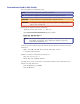
Worksheet Example 2: Daily Configuration Figure 27 continues from worksheet example 1 by showing the ties that make up the configuration of preset 1. Black lines shows one configuration, green lines a second configuration, red lines a third configuration, and blue lines a fourth.
Worksheet Example 3: Test Configuration The A/V system in our fictional organization needs to be fine tuned on a regular basis. Figure 28 shows a typical test configuration, with an Extron video test generator (input 12) generating a test pattern to all outputs that have connected monitors and wall boxes. An audio CD (input 5) is used for evaluating the audio outputs.
MTPX Plus 6400 Series Matrix Switchers • Operation 64 34 50 33 49 Title: 51 35 19 3 51 35 19 3 52 36 20 4 52 36 20 4 53 37 21 5 53 37 21 5 54 38 22 6 54 38 22 6 55 39 23 7 55 39 23 7 57 41 25 9 57 41 25 9 Output destinations 56 40 24 8 56 40 24 8 58 42 26 10 58 42 26 10 59 43 27 11 59 43 27 11 60 44 28 12 60 44 28 12 Configuration Worksheet Fill in the preset number and use colors, or dashes, etc.
Programming Guide This section describes the operation of the MTPX Plus Matrix Switchers using the Simple Instruction Set, including: zz Local Control Ports zz Ethernet (LAN) Port zz Host-to-Switcher Instructions zz Switcher-Initiated Messages zz Switcher Error Responses zz Using the Command/Response Tables zz Special Characters Local Control Ports The switcher has two local ports that can be directly connected to a host device such as a computer running the Extron DataViewer utility or the Hy
Rear Panel Remote Port The default protocol for the 9-pin D female Remote port (see item i and “Remote Connection” on page 17) is as follows: zz 9600 baud • no parity zz 1 stop bit • no flow control • 8 data bits The port can be configured to operate at the 9600, 19200, 38400, or 115200 baud rate. NOTE: Extron recommends leaving this port at 9600 baud only. Front Panel Configuration Port A standard USB cable and the Extron DataViewer utility, version 2.
Establishing a Connection Establish a network connection to an MTPX Plus matrix switcher as follows: 1. Open a TCP socket using the IP address of the switcher. NOTE: If the local system administrators have not changed the value, the factoryspecified default, 192.168.254.254, is the correct value for this field. The switcher responds with a copyright message including the date, the name of the product, firmware version, part number, and the current date/time.
Host-to-Switcher Instructions SIS commands consist of one or more characters per field. No special characters are required to begin or end a command character sequence. When a command is valid, the unit executes the command and sends a response to the host device. All responses from the unit to the host end with a carriage return and a line feed (CR/LF = ]), which signals the end of the response character string. A string is one or more characters.
Exen] The switcher initiates the Exe message when the Executive mode is changed from the front panel. n is the Executive mode is: 0, 1, or 2. Switcher Error Responses When the switcher receives a valid SIS command, it executes the command and sends a response to the host device. If the unit is unable to execute the command because the command is invalid or it contains invalid parameters, the unit returns an error response to the host.
Command/Response Table for SIS Commands Symbol Definitions ] } = CR/LF (carriage return/line feed) (hex 0D 0A) = Carriage return (no line feed, hex 0D) | = Pipe (can be used interchangeably with the } character) • = Space character E X! X@ X# X$ = Escape key (hex 1B) = Input number (for tie) 00 – (maximum number of inputs for your matrix size) (00 = untied) = Output number 01 – (maximum number of outputs for your matrix size) = TP input number 01 – (maximum number of TP inputs for your matrix si
X2@ = Global or room preset number NOTE: X2# A room preset is a stored configuration with all of the outputs assigned to a single room. When a room preset is recalled from memory, it becomes the current configuration. = Name NOTE: X2$ 00 – 64 (global) (00 = current default) or 01 – 10 12 characters maximum for input, output, and global preset names 11 characters maximum for room preset names Upper- and lower-case alphanumeric characters and _ / and spaces are valid.
Command/Response Table for SIS Commands Command ASCII Command Response (Host to Unit) (Unit to Host) Additional Description Create ties NOTES: • The matrix switchers support 1- and 2-digit numeric entries (1*1 and 02*02). • Commands can be entered back-to-back in a string, with no spaces. For example: 1*1!02*02&3*03%. • The quick multiple tie and tie input to all output commands activate all I/O switches simultaneously. • The ! tie command, & tie command, and % tie command can be used interchangeably.
Command/Response Table for SIS Commands (continued) Command ASCII Command Response (Host to Unit) (Unit to Host) Additional Description Audio/RS-232 TP input (wire pair 3 and 6) configuration NOTE: The RS-232 output insert ports, when enabled (EX%*1Lrpt}), override the audio/RS-232 TP input configurations.
Command/Response Table for SIS Commands (continued) Command ASCII Command Response (Host to Unit) (Unit to Host) Additional Description Input skew adjustment Set all input skew adjustment values Example: EX#*X(*X(*X(Iseq} IseqX#*X(*X(*X(] E2*Ø*Ø*4Iseq} IseqØ2*ØØ*ØØ*Ø4] Increment one input skew adjustment value Example: EX#*X1)+Iseq} IseqX#*X(*X(*X(] E2*2+Iseq} IseqØ2*ØØ*ØØ*Ø5] Decrement one input skew adjustment value Read input skew adjustment values EX#*X1)-Iseq} IseqX#*X(*X(*X(] EX#Ise
Command/Response Table for SIS Commands (continued) Command ASCII Command Response (Host to Unit) (Unit to Host) Additional Description Audio output volume NOTE: The table below the commands defines the value of each audio volume step.
Command/Response Table for SIS Commands (continued) Command ASCII Command Response (Host to Unit) (Unit to Host) Additional Description Audio input gain and attenuation NOTE: The set gain (G) and set attenuation (g) commands are case sensitive. Set input audio gain to +dB value Example: Set input audio attenuation to -dB value Increment gain Example: Decrement gain Example: Read input gain X1!*X1(G InX1!•AudX2)] 1*2G InØ1•Aud+Ø2] InX1!•AudX2)] Set input 1 audio gain to +2 dB.
Command/Response Table for SIS Commands (continued) Command ASCII Command Response (Host to Unit) (Unit to Host) Additional Description I/O Grouping NOTES: • The group (X2%) that is assigned in each of the following I/O grouping commands must be 1, 2, 3, 4, or 0 (not grouped). • You must enter an X2% value for each input in your matrix size, such as 48 inputs for an MTPX Plus 4864. • If verbose mode is off (see the “Set verbose mode” SIS command on page 85), the Gri preface is omitted in the response.
Command/Response Table for SIS Commands (continued) Command ASCII Command Response (Host to Unit) (Unit to Host) Additional Description Save, recall, and directly write presets (continued) Write room outputs EX2$,X@1,X@2, ... X@nMR] See notes. MprX2$,X@1,X@2, ... X@n] NOTES: • A room can contain a maximum of 16 outputs (X@s). • An output can belong to only one room. • The maximum number of rooms (X2$s) is 10.
Command/Response Table for SIS Commands (continued) Command ASCII Command Response (Host to Unit) (Unit to Host) Additional Description View ties, gain, volume, mutes, and presets status NOTE: The & read RGB tie command and % read video tie command can be used interchangeably.
Command/Response Table for SIS Commands (continued) Command ASCII Command Response (Host to Unit) (Unit to Host) Additional Description View ties, gain, volume, mutes, and presets (continued) View audio global preset configuration Command description: Response description: Example: (64 x 32 matrix) EX2@*X@*2VC} X!n•X!n+1•...•X!n+15•Aud] Show the audio configuration for preset X2@. Show the input tied to 16 sequential outputs, starting from output X@.
Command/Response Table for SIS Commands (continued) Command ASCII Command Response (Host to Unit) (Unit to Host) Reset whole switcher EZXXX} Zpx] Absolute reset EZQQQ} Zpq] Information request I VX2*XX2(•AX2*XX2(] Request part number N X3)] Additional Description Resets (continued) Clear all ties and presets, reset all all audio gains to 0 dB, and reset volume to 100%. Similar to Reset whole switcher, plus clear all UART ports, reset the IP address to 192.168.254.
Command/Response Table for SIS Commands (continued) Command ASCII Command Response (Host to Unit) (Unit to Host) Additional Description File directory NOTE: The response to the View File Directory command differs, depending on whether the command is sent via an RS-232/RS-422 or Telnet connection, or sent via a web browser connection.
Command/Response Table for IP-Specific SIS Commands Symbol definitions X4) = Matrix name NOTE: (Up to 240 alphanumeric characters) The following characters are invalid or not recommended in the name: {space} + ~ , @ = ` [ ] { } < > ‘ “ ” ; : | \ and ?.
Command/Response Table for IP-Specific SIS Commands Command ASCII Command Response (host to unit) (unit to host) Set matrix name Read matrix name Reset matrix name to factory default Set time and date Read time and date Set GMT offset EX4)CN} ECN} E•CN} Ipn•X4)] X4)] Ipn•X4!] EX4@CT} ECT} EX4$CZ} IptX4@] X4#] IpzX4$] Example: Set Daylight Saving Time Read Daylight Saving Time E8.
Command/Response Table for IP-Specific SIS Commands (continued) Command ASCII Command Response (host to unit) (unit to host) Additional Description IP setup commands (continued) EX5!,X5@CR} Set email recipient IprX5!,X5@,] This command sets the recipient. To receive email notifications, you must then set the events that the switcher reports, using one or more separate Set email events (EM) commands (see below). E72,Jsmith@folklore.netCR} Example: Ipr72,Jsmith@folklore.
Matrix Software This section describes using software to operate the DMS 1600 and DMS 3600, including: zz Matrix Switchers Control Program zz Optimizing the Video zz Button Label Generator Program Matrix Switchers Control Program The Extron Matrix Switchers Control Program communicates with the switcher via the Ethernet LAN port, the serial port, or the USB port to provide an easy way to set up ties and sets of ties.
Installing the Software The program is contained on the Extron Software Products DVD. Install the software as follows: NOTE: For full functionality, install both of the following programs: • • The Matrix Switchers Control Program The Firmware Loader 1. Insert the DVD into the drive. The Extron software DVD window should appear automatically (see figure 29). Figure 29. Software DVD Window NOTE: If the window does not self-open, run Launch.exe from the DVD. 2. Click the Software tab (see figure 29). 3.
NOTES: • For Windows 7, the folder is C:\Program Files (x86)\Extron\Matrix_ Switchers. • The MTPX Plus matrix switcher can support remote control via any of the following three ports: zz Rear panel LAN port — For IP control of the system via an Ethernet LAN, via this RJ-45 connector from anywhere in the world.
Using the Matrix Switcher Control Software Many items found in the Matrix Switchers Control Program are also accessible under SIS control (see Programming Guide). The Matrix Switcher + Help Program provides information on settings and on how to use the control program, itself. NOTE: The first time you connect to the Configuration (USB) port, the Found New Hardware Wizard appears (see figure 31) (see “Activating a USB Port for the First Time,” below).
Starting the program 1. To run the Matrix Switchers Control Program, click Start > Programs > Extron Electronics > Matrix Switchers > MATRIX Switcher + Control Pgm. The Comm Port Selection window (see figure 32) appears. Figure 32. Comm Port Selection Window 2. Choose among the comm port that is connected to the serial port of the switcher, USB, IP [LAN], or Emulate. zz If you selected a comm port, check the baud rate displayed in the Baud Rate field.
NOTE: If the local system administrators have not changed the value, the factory-specified default, 192.168.254.254, is the correct value for this field. b. If the switcher is password protected, click in the Password field and enter the appropriate administrator or user password. c. Click Connect. If you logged on with the administrator password, the program connects you to the matrix switcher with all of the administrator rights and privileges.
Figure 34.
Figure 35.
IP Settings/Options Window The IP Settings/Options window (see figure 36), accessible via the Tools menu, provides a location for viewing and, if connected via either serial port or if logged on via the Ethernet port as an administrator, editing settings unique to the Ethernet interface (see “Ethernet Connection” on page 146 for basic information about IP addresses). None of the fields on this screen can be edited while you are logged on as a user. Figure 36.
Address and Name fields The Matrix IP Address field contains the IP address of the connected matrix switcher. This value is encoded in the flash memory in the switcher. The Gateway IP Address field identifies the address of the gateway to the controlling PC to be used if the matrix switcher and the mail server are not on the same subnet. The Subnet Mask field is used to determine whether the matrix switcher is on the same subnet as the controlling PC when you are subnetting.
Date, Time (local), and GMT (offset) fields The Date field displays the current date in the Greenwich Mean Time zone. The Time (local) field displays the current time in the local time zone. The GMT field displays the amount of time, in hours and minutes, that the local time varies from the GMT international time reference. NOTE: Rather than using the following procedure, you can click the Sync Time to PC button to set the switcher to the internal time of your computer.
NOTES: • Editing the Administrator Password field while connected via the Ethernet port can immediately disconnect the user from the switcher. Extron recommends editing this field using one of the serial ports and protecting the Ethernet access to this screen by assigning an administrator’s password to qualified and knowledgeable personnel only. • An administrator password must be created before a user password can be created.
E-mail Addressee fields The eight E-mail Addressee fields permit the administrator to identify the email addresses of the personnel to whom the matrix switcher emails notification of its failure and repair status. Figure 39 shows a typical email from the switcher. Miles Standish From: Sent: To: Subject: MTPX-FF-FF-09@folklore.net Tuesday, January 4, 2011 10:05 AM Miles Standish MTPX-FF-FF-09 - Fan Failure Tue, 04 Jan 2011 10:05:07 Unit Name = MTPX-FF-FF-09 Unit IP Address = 192-168-254-254 Figure 37.
Updating Firmware The firmware upgrade utility provides a way to replace the firmware that is coded on the control board of the switcher without taking the switcher out of service. Update the switcher firmware as follows: 1. Visit the Extron website, www.extron.com, click the Download tab, and then click the Firmware link (see figure 38). 1 NOTE: The part number, version, release date, and size shown are sample values only. 1 2 3 3 Figure 38. Location of Firmware Upgrade Files 2.
NOTE: The version shown is a sample value only. 4 4 5 Folder where firmware is installed 6 Figure 39.
7. Connect a computer that runs the Windows operating system to either switcher serial port or the switcher LAN port (see “Remote Connection” on page 17). 8. Start the Matrix Switchers Control Program and connect to the matrix switcher (see “Starting the program,” steps 1 through 4, starting on page 90). 9. Click Tools > Update firmware. zz If the switcher is connected via the LAN port, the Select Files window appears (see figure 40) (see “Ethernet-connected firmware upload”, below).
Serial-port-connected firmware upload 10 Figure 41. Extron Firmware Loader Window 10. Select the MTPX Plus matrix switcher and click File > Open. The Choose Firmware File screen appears (see figure 42). 11 11 Figure 42. Choose Firmware File Window 11. Navigate to and select the new firmware file. Click Open. The Choose Firmware File window closes. NOTE: When downloaded from the Extron website, the firmware is placed in a subfolder of C:\Program Files\Extron\Firmware.
Uploading HTML Files You can create customized HTML pages for the switcher to display. The HTML Files List window (see figure 44), accessible via the Tools menu, provides a way to view the contents of the file system of the switcher and upload custom HTML pages to the switcher. 4 7 8 Figure 44. HTML Files List Window NOTES: • The files listed in figure 44 are shown for example only and may not be present on your switcher. • The HTML Files List window is for inserting your own HTML pages.
Windows Buttons, Drop Boxes, and Trash Can The buttons, drop boxes, and trash can on the right side of the Matrix Switchers Control Program window perform the following functions: Power — Unavailable for MTPX Plus matrix switchers, because the switcher power cannot be controlled via software. Executive Mode — Allows you to lock out front panel operations, except for the View mode functions.
Tools menu Assign Device Icons — Displays the complete set of input and output device icons. You can drag any of these icons to the input and output boxes. Edit Device Palette — Allows you to add your own device icon graphics. Audio-Input Gain settings — Displays the audio gain level setting for a single input or for all inputs and allows you to change it. The level is expressed as the magnitude (number of decibels) and polarity (positive, gain or negative, attenuation) of the audio adjustment.
Figure 46. MTPX Picture Settings Window MTPX RS-232 Port settings — Displays the UARTS / Direct-access (via IP) Port Settings window (see figure 47), which allows you to select the input source for output on the audio or RS-232 wire pair and configure the port settings. Available input selections are: zz TP inputs — The audio or RS-232 wire pair (3 and 6) on the TP input zz IP — RS-232 on a UART zz Captive-screw Inputs — The RS-232 direct insert captive screw connector Figure 47.
EDID settings — Displays the Extended Display Identification Data (EDID) Configuration window (see figure 48), which allows you to set each input to a specific EDID value and to save the output resolution to the user-configurable EDID slots. Figure 48. EDID Configuration Window Update Firmware — Allows you to replace the firmware that is coded on the control board of the switcher without taking the switcher out of service (see “Updating Firmware”).
Name Presets — Allows you to assign a name to each of the 64 global presets and 100 room presets. NOTES: • Preset names are limited to 12 upper- and lower-case alphanumeric characters, {space}, _ , and / characters. • The following characters are invalid or not recommended in preset names: + ~ , @ = ‘ [ ] { } < > ’ “ ; : | \ and ?. Show RS-232 Strings — Displays the ASCII commands that are used by the current configuration. You can refer to these for SIS programming.
Ties as Crosspoints — Displays ties as a matrix of inputs and outputs (see figure 51). zz Video and audio ties are indicated as amber check boxes. zz Video-only ties are indicated as green check boxes. zz Audio-only ties are indicate as red check boxes. zz Ties that will take effect when you click the Take button are indicated by a + in the check box. zz Ties that will be broken when you click the Take button are indicated by a – in the check box. Figure 51.
Master-Reset selection Master reset performs all of the following functions: zz zz zz zz zz zz zz Clears all ties Clears all presets Clears all rooms Clears all audio or RS-232 mutes Resets all I/O grouping Sets all input audio levels to unity gain (+0 dB) Sets all output volume levels to 100% (0 dB of attenuation) NOTE: Master reset does not reset the Internet protocol (IP) settings. Using Emulation Mode Emulation mode allows you to set up the software without connecting the switcher.
5. Select MTPX Series as the Matrix Model, select the correct Default Size for the switcher that you are emulating; and the correct Local Inputs DIP Switches emulation (see figure 53). Click OK. Figure 53. Emulate Configuration 6. Continue using the program as described in “Using the program.
Optimizing the Video Each TP input has a level and peaking adjustment. Most MTP transmitters and each MTPX Plus TP output has a pre-peaking feature. TP inputs and outputs have skew adjustments. Set these adjustable features as follows for the best image quality: NOTES: • For all of the settings in this section (with the exception of the Pre-Peak switch on the transmitter in step 1), see the MTPX Pictures settings and MTPX Configuration settings menu items in “Tools menu,” on page 105.
5. Click the Auto-Calibrate Level/Peaking button. After a few moments, the program reports whether or not the calibration succeeded and the original and new settings for the input Pre-Peaking adjustment. 6. Disconnect the power and RJ-45 cables from the MTP signal generator and reconnect them to the MTP transmitter. 7. Repeat steps 1 through 6 for each input. Manual calibration If you choose not to auto calibrate, or if you want to fine tune the adjustment, you can manually set the values as follows: 1.
Output skew 1. Connect an oscilloscope (preferred) or a monitor (acceptable) to the TP output to be adjusted, via an MTP receiver. 2. Apply a crosshatch test pattern to one the local (VGA) inputs. 3. Tie the local input receiving the test pattern signal to the output to be optimized. 4. Use the test equipment or examine the displayed video image with a critical eye to determine which video signal — red, green, or blue — is most shifted to the left. 5.
Button Label Generator Program The Button Label Generator software creates labels that you can place in the translucent covers above and below the input and output pushbuttons. You can create labels with names, alphanumeric characters, or even color bitmaps for easy and intuitive input and output selection (see “Removing and Installing Button Labels” in the “Maintenance and Modifications” section for the procedure for removing and replacing the translucent covers).
Using the Button Label Generator Software 1. To run the Button Label Generator program, click Start > Programs > Extron Electronics > Button Label Generator > Button Label Generator. The Button Label Generator window appears (see figure 57). Figure 57. Button Label Generator window 2. In the Systems selection box, choose the Matrix Switchers 6464 option to match the button label size and quantities for your matrix switcher. 3.
HTML Operation This section describes the operation of the MTPX Plus matrix switcher, including: zz Opening the Embedded Web Pages zz Status Tab zz Configuration Tab zz File Management Tab zz Control Tab zz Special Characters The switcher can be controlled and operated through its LAN port, connected via a LAN or WAN, using a web browser such as Microsoft® Internet Explorer®. The browser display of the status or operation of the switcher has the appearance of web pages.
5. Press the keyboard key. The switcher checks to see if it is password protected. If the switcher is not password protected, it checks and downloads the HTML pages (proceed to step 7). If the switcher is password protected, the switcher downloads the Connect to... page (see figure 58). Figure 58. Connect to... Page NOTE: A User name entry is not required. 6. Click in the Password field and type in the appropriate administrator or user password. Click the OK button. 7.
Status Tab System Status Page The System Status page (see figure 59) provides an overall view of the status of the matrix switcher, including individual voltages, power supply status, and fan status. The System Status page is the default page that the switcher downloads when you connect to the switcher. Access the System Status page from other pages by clicking the Status tab. Refresh Figure 59.
Configuration Tab System Settings Page The MTPX Plus switcher downloads the System Settings page (see figure 60) when you click the Configuration tab. The screen consists of fields in which you can view and edit IP administration and system settings. You can access the Passwords, Email Settings, and Firmware Upgrade pages by clicking the appropriate link (see “Ethernet Connection” on page 146 for basic information about IP addresses and subnetting).
DHCP radio buttons The DHCP On radio button directs the switcher to ignore any entered IP addresses and to obtain its IP address from a Dynamic Host Configuration Protocol (DHCP) server (if the network is DHCP capable). The DHCP Off radio button turns DHCP off. Contact the local system administrator to determine if DHCP is appropriate. IP Address field The IP Address field contains the IP address of the connected switcher. This value is encoded in the flash memory of the switcher.
Date/Time Settings fields The Date/Time Settings fields (see figure 61) provide a location for viewing and setting the time functions. Figure 61. Date/Time Settings Fields Change the date and time settings as follows: 1. Click the drop box for variable to be changed. The adjustable variables are month, day, year, hours, minutes, AM/PM, and (time) zone. A drop-down scroll box appears (the year drop box is selected in figure 61). 2.
Passwords Page Access the Passwords page (see figure 62) by clicking the Passwords link on the System Settings page. Select System Settings Refresh Select Email Settings Select Firmware Upgrade Figure 62. Passwords Page NOTE: If the switcher is password protected, fields on this page can be edited only by people logged in as administrators. The fields on the Passwords page are for entering and verifying administrator and user passwords.
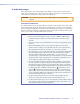
Email Settings Page Reach the Email Settings page (see figure 63) by clicking the Email Settings link on the System Settings page. The Email Settings page has fields for setting up the email notification capabilities of the switcher. For the email settings and for each row of the email notification settings, click the Edit button to make the fields available for editing. The button changes to Save. After editing the associated settings with, click the Save button.
4. Click Save to save the user name and password. Deselecting SMTP authorization Remove SMTP authorization as follows: 1. Click Edit. The button changes to Save. 2. Click (deselect) the SMTP Authorization Required check box. 3. Click Save. Domain Name field The Domain Name field displays the domain name that the MTPX Plus matrix switcher uses to log on to the email server. Standard domain name conventions (for example: xxx.com) apply.
Update the switcher firmware as follows: NOTE: The Firmware Upgrade page is only for replacing the firmware that controls all switcher operation. To insert your own custom HTML pages, see “File Management Page.” 1. Visit the Extron website, www.extron.com, select the MTPX Plus matrix switcher product category, select the latest firmware installation package (*.exe file) for the switcher, and download the file. Note the folder to which you save the firmware file. 2. Run the executable (*.
File Management Tab File Management Page To delete files such as HTML pages from the switcher or to upload your own files to the switcher, click the File Management tab. The File Management HTML page appears (see figure 66). Figure 66. File Management Page NOTE: The files listed in figure 66 are shown for example only and may not be present on your switcher. To delete a file, click the Delete button associated with that file. Upload your own files as follows: 1. Click the Browse button. 2.
Control Tab Set and View Ties Page You can create ties on the Set and View Ties page (see figure 67). Access the Set and View Ties page by clicking the Control tab. Refresh or Select a Different Output Group for Ties Select Picture Settings Select RS-232 Port Settings Select I/O Settings Select Global Presets Figure 67. Set and View Ties Page The page consists of a matrix of input (rows) and output (columns) selection buttons of two colors: zz zz zz zz The amber buttons indicate ties.
Creating or deleting a tie Make or break a tie as follows: 1. Click the Video Only, Audio Only, or Video & Audio button to select video, audio, or both for switching (audio follow or audio breakaway). Each mouse click on a button toggles the other two buttons off. 2. Move the mouse over the matrix of input and output selection buttons. Click a button to: zz Create a pending tie (if a tie does not exist) of the input and output associated with that button.
Picture Settings Page The Picture Settings page provides a way to set the input level and peaking, the output pre-peaking, and the input and output skew settings. Access the Picture Settings page (figure 68) by clicking the Picture Settings link on the Control page. Select an Output Group for Ties Refresh or Select a Different Output Group for Picture Settings Select MTPX Configuration Select RS-232 Port Settings Select I/O Settings Select Global Presets Figure 68.
Changing the input level and peaking Users can set the level and peaking value (from 000 through 255) for each input from the Picture Settings page. Level and peaking can be adjusted to compensate for longer cable runs on the inputs. Change the level and peaking setting for an input in any of the following three ways: zz Use the auto calibration function as follows: 1. Disconnect the power and RJ-45 cables at the MTP transmitter that is connected to the input to be calibrated. 2.
Change the skew setting for an input or output as follows: NOTE: For best results, set all three skew values to 0 ns (see steps 2a and 2b below) before adjusting for misconvergence. 1. Use UTP cable test equipment or examine the displayed video image with a critical eye to determine which video signal, red, green, or blue, is most shifted to the left. TIP: A crosshatch test pattern is ideal for evaluating pair skew. 2. Monitor the displayed image.
MTPX Configuration Page The MTPX Configuration page provides a way to define the content of the audio/RS-232 input, enable the RS-232 output inserts, and tailor the output sync. Access the MTPX Configuration page (figure 71) by clicking the MTPX Configuration link on the Control page. Select an Output Group for Ties Select an Output Group for Picture Settings Refresh Select RS-232 Port Settings Select I/O Settings Select Global Presets Figure 71.
RS-232 Port Settings Page The MTPX RS-232 Port Settings page (see figure 72) allows you to select the input source for output on the audio or RS-232 wire pair and configure the port settings. Select an Output Group for Ties Select a Different Output Group for Picture Settings Select MTPX Configuration Refresh Select I/O Settings Select Global Presets Figure 72.
I/O Settings Page The I/O Settings page provides a way to set the input audio gain and attenuation and the output volume. Access the I/O Settings page (figure 73) by clicking the I/O Settings link on the Control page. Select an Output Group for Ties Select an Output Group for Picture Settings Select MTPX Configuration Select RS-232 Port Settings Refresh Select Global Presets Figure 73.
Changing the input gain and attenuation Users can set the level of audio gain or attenuation (-18 dB to +24 dB) of each input from the I/O Settings page. Audio levels can be adjusted so there are no noticeable volume differences between sources. Change the gain and attenuation setting for an input as follows: 1. Click the Input Audio Level drop box for the desired input. A drop-down scroll box appears (figure 74). Figure 74. Input Audio Level Drop Box 2.
Changing the output volume level Users can set the volume level for each local audio output volume level from the I/O Settings page. Volume is adjustable through a range of zero steps of attenuation (full attenuation, minimum volume) to 64 steps of attenuation (no attenuation, full volume). Change the audio volume setting for an output as follows: 1. Click the Volume drop box for the desired output. A drop-down scroll box appears (figure 75). Figure 75. Volume Drop Box 2.
Global Presets Page You can save and recall global presets from the Global presets page (figure 76). Access the Global presets page by clicking the Global Presets link on the left of the Control page. Select an Output Group for Ties Select an Output Group for Picture Settings Selct MTPX Configuration Select RS-232 Port Settings Select I/O Settings Refresh Figure 76. Global Presets Page Saving a preset Save the current configuration (configuration 0) as a preset as follows: 1.
Recalling a preset To recall a global preset to be the current configuration, click the button associated with the desired preset. Special Characters The HTML language reserves certain characters for specific functions. The switcher does not accept these characters as part of preset names, the name of the switcher, passwords, or locally created file names. The switcher rejects the following characters or they are not recommended: {space} + ~ , @ = ‘ [ ] { } < > ’ “ “ ; (semicolon) : (colon) | \ and ?.
Maintenance and Modifications This section covers corrective maintenance and modifying the MTPX Plus matrix switchers, including: zz Mounting the Switcher zz Removing and Installing a Power Supply Module zz Removing and Installing a Fan Module zz Removing and Installing Button Labels CAUTION: Installation and service must be performed by authorized personnel only.
Mounting Instructions 1. Insert the switcher into the rack, aligning the holes in the mounting bracket with those in the rack. 2. Secure the switcher to the rack using the supplied bolts (see figure 77).
Removing and Installing a Power Supply Module Each power supply module has a 2-color LED that indicates the status of the power supply outputs. If the LED is lit green, the power supply is operating normally. If the LED is lit red, the supply has failed and should be replaced at the earliest opportunity. Removing a Power Supply Module NOTE: The power supply modules are hot-swappable. Any power supply can be removed without powering down the switcher. Remove a power supply module as follows: 1.
Removing and Installing a Fan Module The MTPX Plus 6400 switchers have three fan modules of two different types. The top two fan modules are one type and part number; the bottom fan module has a unique part number. If a fan module fails, it should be replaced at the earliest opportunity. Removing a Fan Module Remove a fan module as follows: NOTE: The fans modules are hot-swappable. Either fan can be removed or installed without powering down the switcher. 1.
Installing a Fan Module 1. Orient the fan to be installed so that the printing on the back of the panel is right-side up. 2. Align the flanges on the fan with the top and bottom fan guides (figure 79). 3. Gently slide the fan into the enclosure until the fan meets resistance. 4. Gently seat the fan in the backplane. 5. Use a screwdriver to tighten the top and bottom screws to lock the fan in place. Removing and Installing Button Labels Figure 81, on page 146 provides strips of blank button labels.
Figure 81.
Ethernet Connection This section provides a high level discussion of the Ethernet connection to the switcher and a primer on the subject of subnetting. Topics that are covered, include: zz Ethernet Link zz Subnetting — A Primer Ethernet Link The rear panel Ethernet connector on the switcher can be connected to an Ethernet LAN or WAN (see item j and “Ethernet Connection” on page 18). Default IP Address To access the MTPX Plus matrix switcher via the LAN port, you need the IP address of the switcher.
Pinging to Determine the Extron IP Address The ping utility is available at the Command prompt. Ping tests the Ethernet interface between the computer and the MTPX Plus matrix switcher. Ping can also be used to determine the actual numeric IP address from an alias and to determine the web address. Ping the switcher as follows: 1. On the Windows task bar, click on Start > Run. 2. At the Open prompt, type command. 3. Click the OK button. 4. At the Command prompt, type ping and then press .
Configuring the Matrix Switcher for Network Use via the ARP Command The ARP (address resolution protocol) command tells your computer to associate the MAC (media access control) address of the MTPX Plus matrix switcher with the assigned IP address. You must then use the ping utility to access the controller, at which point the IP address of the controller is reconfigured. Use ARP to configure the IP address as follows: 1.
6. After verifying that the IP address change was successful, enter and issue the arp –d command at the Command prompt. For example: arp –d 10.13.197.7 removes 10.13.197.7 from the ARP table or arp –d* removes all static IP addresses from the ARP table. Connecting as a Telnet Client The Telnet utility is available via the Command prompt. Telnet allows you to input SIS commands to the MTPX Plus matrix switcher from the PC via the Ethernet link and the LAN.
Telnet Tips It is not the intention of this guide to detail all of the operations and functionality of Telnet; however, some basic level of understanding is necessary for operating the MTPX Plus matrix switcher via Telnet. Open Connect to the MTPX Plus matrix switcher using the Open command. Once you are connected to the switcher, you can enter the SIS commands the same as you would if you were using the RS-232 of RS-422 link. Connect to the MTPX Plus matrix switcher as follows: 1.
Local echo Once connected to the MTPX Plus matrix switcher, by default, Telnet does not display your keystrokes on the screen. SIS commands are typed in blindly and only the SIS responses are displayed on the screen. To command Telnet to show keystrokes, at the Telnet prompt, type set local_echo and then press before you open the connection to the switcher. With local echo turned on, keystrokes and the responses of the switcher are displayed on the same line.
Subnetting — A Primer It is not the purpose of this guide to describe TCP/IP protocol in detail. However, some understanding of TCP/IP subnetting (a subnet is a subset of a network — a set of IP devices that have portions of their IP addresses in common) is necessary in order to understand the interaction of the MTPX Plus matrix switcher and the mail server gateway.
Determining Whether Devices Are on the Same Subnet To determine the subnet, the IP address of the local device is compared to the IP address of the remote device (see figure 87). The octets of each address are compared or not compared, depending on the value in the related subnet mask octet. zz If a subnet mask octet contains the value 255, the related octets of the IP addresses of the local device and the remote device are unmasked. Unmasked octets are compared (indicated by ? in figure 87).
Reference Information This section discusses the specifications, part numbers, and accessories for the MTPX Plus 6400 Series Matrix Switchers.
Video output — local Number/signal type ������������������������ 4 analog RGBHV, RGBS, RGsB, RsGsBs, component video (bi-level and tri-level sync), S-video, composite video Connectors ������������������������������������ 4 female 15-pin HD Nominal level ��������������������������������� 1 Vp-p for Y of component video and S-video, and for composite video 0.7 Vp-p for RGB and for R-Y and B-Y of component video 0.
Audio output — local Number/signal type ������������������������ Connectors ������������������������������������ Impedance ������������������������������������� Gain error �������������������������������������� Maximum level (=10k ohms) ���������� Maximum level (600 ohm) �������������� 8 dual mono, balanced/unbalanced (8) 3.
General Recommended cable type �������������� Shielded or unshielded CAT 5/5e/6/7 or Extron Enhanced Skew-Free™ A/V UTP Power �������������������������������������������� 4*, 100 VAC to 240 VAC, 50-60 Hz; internal power supplies, 400 watts each *A redundant power supply is standard.
Part Numbers MTPX Plus Matrix Switcher Part Numbers Matrix Switcher Part Numbers Part Number MTPX Plus 4848 60-1038-01 MTPX Plus 4864 60-1039-01 MTPX Plus 6432 60-1040-01 MTPX Plus 6448 60-1041-01 MTPX Plus 6464 60-1042-01 Included Parts These items are included in each order for an MTPX Plus matrix switcher: Part Part Number Power supply modules (4) 70-772-01 Fan modules Fans 1 and 2 (numbered from the top) 70-931-01 Fan 3 (numbered from the top) 70-932-01 MTP signal generator 70-729-0
Optional Accessories Remote control accessories, and connectors Part Number MKP 1000 remote keypad Black 60-239-02 White 60-239-03 WT (water-tight) black 60-239-52 WT (water-tight) white 60-239-53 MCP 1000M (matrix control panel) 60-298-01 MCP 1000S (secondary control panel) 60-298-02 MKP 2000 X-Y remote control panel, black 60-682-02 MKP 3000 X-Y Remote Control Panel with LCD Display, black 60-708-02 MKP 3000 MAAP Black 60-709-02 White 60-709-03 MKP 3000 L (lectern mounted) 60-709-22
Extron® Warranty Extron Electronics warrants this product against defects in materials and workmanship for a period of three years from the date of purchase.