Setup Guide SMX System MultiMatrix Switchers 68-1452-50 Rev.
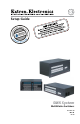
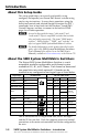
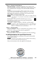
Typical SMX switcher application HD Camera HD-SDI Camera 1 2 MODE Tx Rx OPTICAL FOX HDSDI 1 2 BUFFERED OUTPUTS DVD Player DVD/VCR Combo PCs Compact HDTV Camera Systems Transceiver Extron FOX HD-SDI HD/SDI IN RS232/RS422 REMOTE ® US LISTED IT23 I.T.E.
Table of Contents Chapter One • Introduction .........................................................1-1 About this Setup Guide ................................................................1-2 About the SMX System MultiMatrix Switchers .................1-2 Chapter Two • Installation ...........................................................2-1 Rear Panel ...........................................................................................2-2 Installation and cabling .............................
Table of Contents, cont’d Chapter Four • SIS™ Programmer's Guide .......................4-1 Selected SIS™ Commands .............................................................4-2 Establishing a network (Ethernet) connection .......................4-2 Connection time-outs ..............................................................4-2 Number of connections ...........................................................4-2 Verbose mode ..........................................................................
SMX System MultiMatrix Switchers 1 Chapter One Introduction About this Manual About the SMX System MultiMatrix Switchers
Introduction About this Setup Guide This setup guide helps you to easily and quickly set up, configure, and operate your Extron SMX matrix switcher using step by step instructions. It covers basic operations using the front panel controls and selected Simple Instruction Set (SIS™) commands, how to load and start the Windows®-based SMX Control Program, and how to connect to the built-in HTML pages for switcher operation.
SMX System MultiMatrix Switchers 2 Chapter Two Installation Rear Panel Front Panel Overview
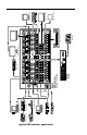
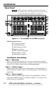
Installation Rear Panel N SMX switchers are available in 3U, 4U, or 5U frames. The number, type, and arrangement of I/O boards in your switcher may differ from that shown in figure 2-1.
Step 4 — Connect control devices LAN Ethernet port — Connect to an Ethernet LAN or WAN via this RJ-45 connector b to control the switcher from a remote location, using a PC’s Internet browser. See page A-2 for network cable termination method. The Ethernet connection indicator LEDs marked “Link” and “Act”, indicate the status of the SMX’s Ethernet connection. The Link LED lights green when connected to an Ethernet LAN, and the Act LED flickers amber, as the devices communicate.
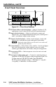
Installation, cont’d Front Panel Overview 1 4 I/O PLANE SELECT 0 1 2 3 4 5 6 7 8 9 10 11 12 13 14 15 INPUTS 2 CONTROL 1 2 3 4 5 6 7 8 9 10 11 12 13 14 15 16 CONFIG 1 2 3 4 5 6 7 8 9 10 11 12 13 14 15 16 ENTER PRESET P O W E R OUTPUTS VIEW ESC MAIN I/O CARDS SMX SERIES SWITCHER 3 6 5 Figure 2-3 — Front Panel features a I/O Plane address selection buttons — Select I/O planes (0-15), and buttons 0 and 1 select RS-232 or RS-422 communication.
SMX System MultiMatrix Switchers 3 Chapter Three Front Panel Operation Creating Ties Viewing Ties Muting or Unmuting Outputs Removing Ties I/O Presets Setting the Front Panel Locks (Executive Modes) Adjusting the Input Audio Level Adjusting the Output Audio Volume Reset Levels
Front Panel Operation Creating Ties Step 1 – Press and release Esc. C O NT R O L ENTER PRESET VIEW ESC Flashes green once. Clears pending changes. Step 2 – Press and release the desired I/O Plane button. I/O PLANE SELECT 0 1 2 3 4 5 6 7 8 9 10 11 12 13 14 15 I/O plane and input buttons lights green if on a video plane, red if on an audio plane, or amber if on a video and audio plane. Step 3 – Press desired Input button.
Viewing Ties Step 1– Press the View button. C O NT R O L ENTER PRESET VIEW ESC View button lights red I/O PLANE SELECT 0 1 2 3 4 5 6 7 8 9 10 11 12 13 14 15 Last plane button used lights. INPUTS 1 2 3 4 5 6 7 8 9 10 11 12 13 14 15 16 1 2 3 4 5 6 7 8 9 10 11 12 13 14 15 16 OUTPUTS Untied buttons light No input buttons light. Step 2 – To view ties for another plane, press that plane button.
Front Panel Operation, cont’d Muting or unmuting Outputs N When front panel is in lockout mode 2, the output mute status can be viewed only. No changes (i.e. muting or unmuting) can be made from the front panel. Follow steps 1 – 3 of “Viewing Ties”. Step 4 – To mute outputs, press and hold lit or unlit output button(s) for 2 seconds. To unmute outputs, press and hold blinking output button(s) for 2 seconds.
I/O Presets The SMX has a total of thirty-two global preset (using I/O buttons 1-16) and ten plane preset (input buttons 1-10) addresses available. Global preset — Saves and recalls configurations for all planes. Use the input buttons (for presets 1 through 16) and output buttons (for presets 17 through 32) to save any current tie configuration to any one of the presets. Plane preset — Saves and recalls the configurations for a specific plane, without affecting the other plane connections.
Front Panel Operation, cont’d Saving or recalling a global preset Step 1 – Press and release Esc. C O NT R O L ENTER PRESET VIEW ESC Flashes green once and clears pending changes. Step 2 – To save a global preset, press and hold the Preset button (for about 2 seconds). – To recall a global preset, press and release the Preset button. N Saving a preset – Preset button flashes red (shown here). Recalling a preset – button lights red.
Saving or recalling a plane preset Follow step 1 of “Saving or recalling a global preset”. Step 2 – To save a plane preset, press and hold the Preset button (for 2 seconds). – To recall a plane preset, press and release the Preset button. N Saving a preset – Preset button flashes red (shown here). Recalling a preset – Preset button lights red. C O NT R O L ENTER PRESET VIEW ESC N At this time all lit presets are global presets, not plane presets. Step 3 – Press the desired plane button (here plane 0).
Front Panel Operation, cont’d Lock mode 2 (Advanced Executive mode) — Basic functions are unlocked. Advanced features are locked and can be viewed only (default mode). Basic features consist of: Making ties, saving and recalling presets, setting input audio gain and attenuation, and changing lock modes. Advanced features consist of: Setting video and audio output mutes, setting audio output volume, setting RGB delay (VGA, RGBHV boards), setting the rear panel remote port protocol and baud rate.
Adjusting the Input Audio Level The audio level of each input can be displayed and adjusted through a range of -18 dB to +24 dB. The level can be adjusted from the front panel, or via RS-232or Ethernet connection. N Refer to the SMX User's Manual for adjustment methods using SIS commands. Using the front panel Example: Change inputs 8's audio level settings from -9dB to +20 dB. Input 8 is on audio plane 4. Step 1 – Press and release Esc. Flashes green once and clears pending changes.
(See Input Audio Level Table for button lighting and dB levels.) N View button lights red and output buttons are red when current audio level is negative dB, and Esc button lights red and output Front Panel Operation, cont’d buttons are green when it is positive dB. Step 5 – Press and hold View to decrease or Esc to increase audio level (here Esc). C O NT R O L ENTER PRESET VIEW ESC Selected control button lights red.
N There is only one audio level setting per input and one per output on an audio plane. The audio level and volume is shared by the left and right inputs and outputs. Audio levels and volumes are stored in nonvolatile memory. When power is removed or restored, settings are retained. If the audio is set to "follow all", at initial selection (step 2) the I/O plane and tied I/O buttons light amber. When an input or output button is held (step 3), the plane blinks red.
Front Panel Operation, cont’d Output Audio Volume Table Volume % dB Attenuation Buttons lit SIS commnand Volume % dB Attenuation Buttons lit SIS commnand 100 0 16 plane*out# *64V/v 52.0 32 8 plane*out# *32V/v 98.5 1 16 63 50.5 33 8 31 97.0 2 slow 62 49.0 34 slow 30 95.5 3 slow 61 47.5 35 slow 29 94.0 4 15 60 46.0 36 7 28 92.5 5 15 59 44.5 37 7 27 91.0 6 slow 58 43.0 38 slow 26 89.5 7 slow 57 41.5 39 slow 25 88.0 8 14 56 40.
Reset Levels The rear panel has a recessed Reset button (see page 2-2, c) that initiates four levels of resets (numbered 1, 3, 4, and 5). Use a pointed stylus, ballpoint pen, or Extron Tweeker to access it and enter the reset levels. See the table on next page for a summary of the modes. C Review the reset modes carefully. Using the wrong reset mode may result in unintended loss of flash memory programming, port reassignment, or a controller reboot.
Front Panel Operation, cont’d Reset Mode Table Mode Action Result 1 Hold down the recessed Reset button while applying power to the switcher. Defaults switcher to factory installed firmware. 3 Hold down the Reset button for 3 seconds, until the Reset LED blinks once, then press Reset momentarily (<1 second) within 1 second. Mode 3 turns events on or off. During resetting, the Reset LED flashes 2 times if events are starting, 3 times if events are stopping.
SMX System MultiMatrix Switchers 4 Chapter Four SIS™ Programmer's Guide Selected SIS™ Commands SIS Command Tables
Programmer's Guide Selected SIS™ Commands The switchers use Simple Instruction Set (SIS) commands for operation and configuration. These commands can be run from a PC connected to either of the switcher’s serial ports or the Ethernet port. See b and d on page 2-2, and f on page 2-6, for connection information. N The tables that begins on the page 4-4 are a partial list of SIS commands. For a complete list, refer to the SMX User's Manual, chapter 4, “Programmer’s Guide”.
Host-to-switcher instructions SIS commands consist of one or more characters per command field and do not require any special characters to begin or end the sequence. Switcher response to an SIS command ends with a carriage return and a line feed, which signals the end of the character string (string = one or more characters).
Command ASCII command (host to switcher) Response (switcher to host) Additional description Also refer to the SMX System MultiMatrix Switchers User’s Manual at www.extron.com. SMX System MultiMatrix Switchers • Programmer's Guide Output switching by plane N The & tie command for RGBHV and the % tie command for video can be used interchangeably. The ! tie command can be used for switching both video signals and audio signals with the same plane address.
Command ASCII command Response Also refer to the SMX System MultiMatrix Switchers User’s Manual at www.extron.com. SMX System MultiMatrix Switchers • Programmer's Guide (host to switcher) (switcher to host) E+QX2@*X@*X# ! ...X2@*X@*X#$ } Qik ] Additional description Quick multiple tie Make multiple ties Example: N E+Q01*3*4!01*3*5%.. 01*3*6$] This command activates all I/O switches simultaneously. Qik] Make multiple ties with one command entry. Tie plane 01's input 3 to outputs 4, 5, and 6.
ASCII command Response Additional description (host to switcher) (switcher to host) X2@*X#*1Z/z X2@*X#*0Z/z X2@*X#Z/z X2@*1*Z/z X2@*0*Z/z X2@AmtX#*1] X2@AmtX#*0] X(] X2@Amt00*1] X2@Amt00*0] Mute audio output X#. E X2@VM} X1$1X1$2...X1$n] Mut X2@•X1$1X1$2...X1$n] View output mute for plane X2@. Audio mute Also refer to the SMX System MultiMatrix Switchers User’s Manual at www.extron.com.
Command ASCII command Response Additional description Also refer to the SMX System MultiMatrix Switchers User’s Manual at www.extron.com. SMX System MultiMatrix Switchers • Programmer's Guide (host to switcher) (switcher to host) Save current ties as a plane preset X2@*X1!*0, X2@SprX1!] Save the current set of ties as plane preset X1!. The command character is a comma (,). Recall a plane preset X2@*X1!*0. X2@RprX1!] Recall plane preset X1!, which becomes the current configuration.
ASCII command (host to switcher) Response (switcher to host) Additional description Information requests Also refer to the SMX System MultiMatrix Switchers User’s Manual at www.extron.com. SMX System MultiMatrix Switchers • Programmer's Guide N Firmware version/part number/information is for the primary frame only. Query firmware version Q X2!] Example: Q Query system status Example: 1.00] Ver01*X2!] The firmware version is 1.00 (sample value).
Command ASCII command Also refer to the SMX System MultiMatrix Switchers User’s Manual at www.extron.com. SMX System MultiMatrix Switchers • Programmer's Guide Query part number and slot information Response Additional description (host to switcher) (switcher to host) N *N 60-xxx-yy 60-xxx-yy.X2#n1X2#n2X2#n3..... X2#n6/8/10] Pno 60-xxx-yy.X2#n1X2#n2X2#n3.... X2#n6/8/10] (verbose response) Example: *N Pno60-857-01.
ASCII command (host to switcher) Response (switcher to host) Additional description EDID (Extended Display Identification Data) commands Also refer to the SMX System MultiMatrix Switchers User’s Manual at www.extron.com.
Command ASCII command Response Also refer to the SMX System MultiMatrix Switchers User’s Manual at www.extron.com.
Also refer to the SMX System MultiMatrix Switchers User’s Manual at www.extron.com. SMX System MultiMatrix Switchers • Programmer's Guide ASCII command IP setup commands cont'd Set verbose mode E X3&CV} Vrb X3&] E CV } X3& ] (host to switcher) Response (switcher to host) Additional description Enable or disable verbose mode and/or tagged responses, in which additional information is given in query response.
SMX System MultiMatrix Switchers 5 Chapter Five Configuration and Control Installing and Starting the SMX Control Program Accessing the HTML Pages Using the Web Pages to Configure the SMX
Configuration and Control Installing and Starting the SMX Control Program The switcher can be operated via the Windows®-based SMX Control Program. This program is contained on the Extron Software Products CD-ROM (included with the switcher). Install and run this program on a Windows-based PC connected to either of the switcher’s serial ports or the Ethernet port. See b and d, on pages 2-2 and 2-3, or f on page 2-4, for connection information. It cannot be run from the CD-ROM.
Starting the program 1. Click Start > Programs > Extron Electronics > SMX Control Program > SMX Control Pgm icon. The Comm Port Selection window appears. 2. Choose the comm (serial) port that is connected to the switcher or IP [LAN]. N For a comm port, check the baud rate displayed in the comm port selection window. To change the baud rate, click the Baud button, double-click the desired baud rate. Click OK. If you selected a comm port in step 2, the SMX Control Program is ready for operation. 3.
Configuration and Control, cont'd Accessing the HTML Pages Another way to operate the switcher is via its factory-installed HTML pages, which are always available and cannot be erased or overwritten. The switcher’s HTML pages are accessible through its LAN port, connected via a LAN or WAN, using a Web browser such as Microsoft® Internet Explorer®. See d on page 2-3 for connection information.
Using the Web Pages to Configure the SMX The switcher settings can be configured via LAN /WAN web pages using a suitable Internet browser (Internet Explorer®, Firefox®). To view and configure the switcher via Web pages: If not already done, connect the SMX to a PC using the rear 1. panel RJ-45 LAN connector. 2. Open the Internet browser on the host computer, and in the address bar type the IP address for the SMX switcher. N The default IP address is 192.168.254.254.
Configuration and Control, cont’d Configuration page This page gives access to the following major settings: System Settings, Passwords, Email Settings and Firmware Upgrade. Click in the left column to access each page section. File Management page This page allows files to be uploaded and deleted from the server within the SMX. Control page This page has two sections: User Control and Presets.
SMX System MultiMatrix Switchers A Appendix A Reference Material Cable and Connector Wiring Installing the Input/Output Boards
Reference Material N For SMX series specifications refer to the SMX User's Manual online or on the supplied CD, or to the product's Web page online at www.extron.com. Cabling and Connector Wiring Ethernet cables must be of the correct type, properly terminated relevant to the application, and with the correct pinout. Choosing a network cable Use Category (CAT) 3, 4, 5, 5e, or 6 unshielded twisted pair (UTP) or shielded twisted pair (STP) cables, terminated with RJ-45 connectors.
Wiring audio connectors Audio input connectors — Connect audio input devices to the 3.5 mm, 5-pole captive screw connectors (up to two groups of eight sets possible). Wire the input connector for the appropriate signal type, as shown below.
Reference Material, cont’d Installing the Input/Output Boards The I/O boards used in any installation will vary and can be installed and changed as desired. N All boards are hot-swappable, and can be installed without shutting down the switcher and removing the power. Installing new boards into an empty SMX frame 1. Remove as many of the blanks panels from the rear of the unit as needed. 2. Slide the I/O board into the open slot, carefully aligning it with the plastic slides in the frame (see figure).
Extron’s Warranty Extron Electronics warrants this product against defects in materials and workmanship for a period of three years from the date of purchase.
Extron USA - West Headquarters +800.633.9876 Inside USA / Canada Only +1.714.491.1500 +1.714.491.1517 FAX Extron USA - East Extron Europe Extron Asia Extron Japan Extron China Extron Middle East +800.633.9876 +800.3987.6673 +800.7339.8766 +81.3.3511.7655 +81.3.3511.7656 FAX +400.883.1568 +971.4.2991800 +971.4.2991880 FAX +1.919.863.1794 +1.919.863.1797 FAX +31.33.453.4040 +31.33.453.4050 FAX +65.6383.4400 +65.6383.