
Setup guide

SMX System MultiMatrix Switchers • Introduction
Introduction
1-2
Also refer to the SMX System MultiMatrix Switchers User’s Manual at www.extron.com.
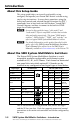
About this Setup Guide
This setup guide helps you to easily and quickly set up,
configure, and operate your Extron SMX matrix switcher using
step by step instructions. It covers basic operations using the
front panel controls and selected Simple Instruction Set (SIS
™
)
commands, how to load and start the Windows
®
-based SMX
Control Program, and how to connect to the built-in HTML
pages for switcher operation.
N
As used in this guide the terms “video model” and
“audio model” refers to any SMX switcher that switches
video and audio respectively. The terms "SMX matrix
switcher", SMX switcher", "SMX", and "switcher" are
refer to a typical SMX System MultiMatrix Switcher.
N
For detailed information on the product described in this
guide, refer to the SMX System MultiMatrix Switchers
User’s Manual (also referred to as the SMX User's
Manual), available at www.extron.com, or the Extron CD.
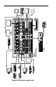
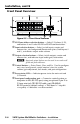
About the SMX System MultiMatrix Switchers
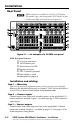
The Extron SMX System MultiMatrix Switcher is a rack
mountable, modular, configurable, multi-format system
available in 3U, 4U, or 5U frames. Each frame has horizontal
rear panel slots into which optional I/O boards can be
inserted in any configuration and signal type as listed below:
L R
8x4 (1)
Composite video
S-video
VGA
SDI and HDSDI
Audio (analog)
Signal Type
I/O Connector
I/O size (slots used)
BNC
Captive screw
Wideband video
BNC
BNC
15-pin HD
BNC
DVI/DVI-Pro
DVI-I (Digital Only)
8x8 (2)
8x8 (1)
8x4 (1)
4x8 (2)
8x4 (1)
8x4 (2)
8x4 (1)
8x4 (2)
8x8 (1)
8x8 (2)
8x8 (1)
8x8 (1)
8x4 (2)
16x16 (4)
16x16 (2)
16x16 (2)
16x16 (4)
16x16 (2)
S-video
mini DIN
8x4 (1)
8x8 (1)
16x16 (2)
16x16 (2)
8x8 (2)
4x4 (1)
4x4 (1)
Fiber optic
8x8 (1)
Sync
8x8
H or V (1)
16x16
H or V (2)
BNC
8x8
HV (2)
Optical (SFP)
HDMI
4x8 (2) 8x4 (2)
8x8 (2)
4x4 (1)
HDMI
16x16 (2)
The 3U enclosure has six single board slots, the 4U has eight
and the 5U has ten slots. Each slot supports power and control
connections to the main unit controller and can be configured by
the user.