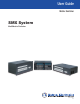
User Guide Matrix Switcher SMX System MultiMatrix Switcher 68-1452-01 Rev.
Safety Instructions • English WARNING: This symbol, , when used on the product, is intended to alert the user of the presence of uninsulated dangerous voltage within the product’s enclosure that may present a risk of electric shock. ATTENTION: This symbol, , when used on the product, is intended to alert the user of important operating and maintenance (servicing) instructions in the literature provided with the equipment.
FCC Class A Notice This equipment has been tested and found to comply with the limits for a Class A digital device, pursuant to part 15 of the FCC rules. The Class A limits provide reasonable protection against harmful interference when the equipment is operated in a commercial environment. This equipment generates, uses, and can radiate radio frequency energy and, if not installed and used in accordance with the instruction manual, may cause harmful interference to radio communications.
Conventions Used in this Guide Notifications The following notifications are used in this guide: CAUTION: A caution indicates a situation that may result in minor injury. ATTENTION: Attention indicates a situation that may damage or destroy the product or associated equipment. NOTE: A note draws attention to important information. TIP: A tip provides a suggestion to make working with the application easier.
Contents Introduction.................................................... 1 SMX Series Description....................................... 1 Definitions............................................................ 3 Features.............................................................. 4 Installation and Cabling................................ 6 UL Safety Requirements...................................... 6 Rear Panel Features and Connections................. 7 Power and Control Connections.................
SMX Control Software................................. 59 Ethernet Control........................................ 106 Installing and Starting the SMX Control Program........................................................... 59 Installing the Program.................................... 59 Starting the Program..................................... 60 Using Emulation Mode...................................... 61 Using the Program............................................ 62 Control Program Menus and Pages.
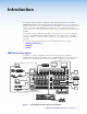
Introduction This guide contains installation, configuration, and operating information for the Extron SMX MultiMatrix Switcher with optional input and output (I/O) boards. It covers operations using the front panel controls and Simple Instruction Set (SIS™) commands. It also describes how to load and start up the SMX Control Program that runs on Windows® operating systems and how to connect to the built-in HTML pages for additional methods of operating the SMX.
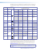
The table below gives a list of available I/O boards, the number and type of connectors, and the number of slots used by any given board. For example, from the first row, the SMX 84 V is an 8x4 (8 inputs by 4 outputs) composite video board. It takes up one slot, and has BNC connectors.
Definitions The following terms are used throughout this guide: Tie — An input-to-output connection Set of ties — An input tied to two or more outputs. An output can never be tied to more than one input Configuration — One or more ties or one or more sets of ties Current configuration — The configuration that is currently active in the switcher (also called configuration 0) Plane — A board or set of boards that will be switched together. Plane numbers are set by a rotary switch on each board.
Features Hot swappable input/output boards and SFP modules — Any board or SFP module can be added or replaced without taking the unit out of service or removing the power. Channel to channel isolation — Each I/O board provides isolation between channels and extremely low electrostatic emissions. Quick-Switch Front Panel Controller (QS-FPC™) — The QuickSwitch FPC allows for touch-of-a-button input and output selection and switching.
Three front panel security lockout modes (executive modes) — If a matrix switcher is installed in an area where operation by unauthorized personnel may be a problem, either of two security lockout modes can be implemented (the third mode is unlocked). When a front panel locked mode is enabled, a special button combination or SIS command is required to unlock the front panel controller and make the front panel operational.
Installation and Cabling This section describes how to install the I/O boards and connect cables to the SMX device. Topics in this section include: • UL Safety Requirements • Rear Panel Features and Connections • SMX Frame and I/O Board Installation • Wiring the Audio Connectors UL Safety Requirements The requirements listed below pertain to the safe installation and operation of this SMX. Important safety instructions: 1. Read these instructions. 2. Keep these instructions. 3. Heed all warnings. 4.
Rear Panel Features and Connections 2 1 3 4 1 OUT IN 2 OUT IN OUT 3 IN 4 OUT 2 1 3 IN 6 OUT IN 4 7 OUT IN 5 8 OUT IN 6 FIBER OPTIC 4 SDI / HDSDI INPUTS 5 8 7 6 22 11 ADDRESS 33 44 RESET 7 8 77 66 COMPUTER OUT 1 2 3 4 5 6 7 8 ACT LINK 55 SDI / HDSDI OUTPUTS COMPUTER IN RS232/RS422 LAN 3 DVI-D OUTPUTS 5 OUT DIGITAL VIDEO 4 2 IN ADDRESS FIBER OPTIC REMOTE 3 2 1 ADDRESS DVI-D INPUTS ADDRESS 1 2 3 4 5 6 7 8 8 S-VIDEO 2 1 3
Reset button and Ethernet cable termination RESET It is essential that the Ethernet cables used be the correct type of cable and terminated with the correct pinout. The cable can be terminated as either a patch cable or a crossover cable and must be properly terminated relevant to the application (see Ethernet Control on page 106 for termination details). c Reset button (recessed) — Press and hold in this recessed button to reset the SMX to the default (factory setting) mode.
f SMX 44 FOX 4G MM — Connect fiber optic input cables from a signal source to input ports and from output ports to a suitable display. LEDs light when signals are present. 1 OUT IN OUT 2 IN 3 OUT IN 4 OUT IN FIBER OPTIC g 5 OUT IN 6 OUT IN ADDRESS 7 OUT IN 8 OUT IN FIBER OPTIC SMX 88 HD-SDI — Connect SDI, HD-SDI, or dual link HD-SDI input sources to any of the BNC input connectors. Connect suitable display devices to the BNC output connectors.
Other I/O Boards SMX 84 USB Connect host devices (such as a PC) to any of the USB Type B Hosts ports (inputs). Connect suitable USB devices (such as a mouse or keyboard) to any of the USB Type A Device Hubs ports (outputs). NOTES: • There are 3 USB hubs in series within the USB boards. Per USB specifications, up to 5 USB hubs can be used in a system. • USB boards cannot be cascaded. • Appropriate USB Type A to USB Type B cables or adapters may be required for USB Type B input signals.
NOTES: • The boards are hot-swappable: they can be installed or removed without turning off or disconnecting the power. However, turning the power off prior to installing or removing boards is recommended. • Use ESD precautions when installing a board to avoid damaging it. Keep the board in the anti-static bag until needed. Use proper grounding techniques during installation. See Frames and I/O Boards on page 114 for a full list of available boards for the SMX.
Wiring the Audio Connectors Connect audio input devices to the 3.5 mm, 5-pole captive screw connectors (up to two groups of eight sets possible). Wire the input connectors as shown in figure 5. L L Tip Ring Sleeves Tip Ring Tip Ring Sleeve R R Balanced Audio Output Input Balanced Mono Input (high impedance) L L Tip Sleeve Tip Sleeve Tip Sleeve R R Unbalanced Stereo Input Unbalanced Mono Input Do not tin the wires! Figure 5.
Operation This section discusses the operation of an SMX series device through the front panel buttons and includes: • Front Panel Overview • Powering Up • Front Panel Operation • Configuring the Rear Panel RS232/RS422 Port • Viewing and Adjusting the Audio Input Level • Viewing and Adjusting the Audio Output Volume • Using Reset Levels • Troubleshooting Front Panel Overview SMX controls and indicators are shown in figure 8.
I/O Plane Selection Buttons a Plane selection buttons — The buttons, labeled 0 through 15, allow plane selection and identify any tied inputs and outputs on the selected plane. These correspond to the board rotary switch settings. Input and Output Buttons b Input selection buttons — Input buttons 1 through 16 select inputs to tie to outputs, remove or replace ties, and to view ties. Any input can be tied to any output as video, audio, or both (see the Front Panel Operation on page 16 for more details).
Control Buttons d Control selection buttons — These four buttons give direct access to the enter (save), preset, view, and Esc (exit) controls. Each button has a separate function. NOTES: • See Configuring the Rear Panel RS232/RS422 Port on page 26 for serial port configuration details. • See Setting the Front Panel Locks (Executive Modes) on page 25 for executive modes details.
Front Panel Configuration Port f Configuration port — This 2.5 mm port (jack) can be used to configure the SMX during setup via RS-232, and has an independent protocol from the primary RS-232 port on the rear panel. Use the 2.5 mm configuration cable, part number 70-335-01 (see figure 9) for connection to your PC serial port. RS-232 protocol (default): 9600 baud, 1 stop bit, no parity, 8 data bits, no flow control.
• If any associated (lit) output button (an existing tie) is toggled off by pressing the button and the Enter button is pressed, the existing tie to that output is lost. • Ties can be made using SIS commands via RS-232, RS-422, Ethernet, the SMX Control Software program, or the internal Web pages (see SIS Configuration and Control on page 34 for RS-232 and RS-422 control, SMX Control Software on page 59 for Software, or HTML Configuration and Control on page 87 for HTTP methods).
Viewing Ties Any existing input to output tie can be viewed. An example of viewing a set of video or audio ties The following shows how to view existing ties on any allocated plane (here planes 0 and 2). 1. Press and release the View button (lights red). The last plane button used (here 0) lights green, and untied output buttons light the appropriate color for the plane signal type, (green for video, red for audio, amber for both). NOTE: If all output buttons light, no outputs are tied.
Removing Ties Any video or audio tie can be removed from an existing set of ties. An example of removing ties from an existing set of ties In this example, input 3 on video plane 0 is already tied to outputs 2, 4, 6, and 7. The ties to outputs 4 and 7 are to be removed. 1. Press and release plane button 0 which lights green. Input button 1 lights the plane signal type: green for video, red for audio, amber for video and audio. 2. Press and release input button 3 (lights).
Replacing Ties An input tied to an output can be replaced with another input, as long as that input is of a similar type or plane (for example, video for video and audio for audio). An example of replacing an existing tied input with another input In the following example, input 2 on video plane 0 is tied to output 1, 4, and 8. The input 2 signal to output 1 is to be replaced by the input 7 signal, also on plane 0, and already tied to outputs 3 and 6. 1. Press and release plane button 0. It lights green.
Muting an output To mute an output signal, do the following: 1. Press and release the Esc button to clear all pending changes. 2. Press and release the View button, which lights red. The previously selected plane button and untied output buttons light (see figure 17), or flash if the outputs are already muted. Tied outputs remain unlit.
Unmuting an output To unmute an output signal, do the following: 1. Press and release the Esc button to clear all pending changes. 2. Press and release the View button, which lights red. 3. Press and hold the desired muted output button, until the button light ceases to flash and remains lit (approximately 2 seconds). The signal is now unmuted. NOTE: Output buttons with muted signals flash the appropriate color (green for video, red for audio, or amber for both).
Saving or recalling a global preset 1. Press the Esc button to clear all pending changes. The button flashes green once. 2. Saving a global preset — Press and hold the Preset button until it flashes red. OR Recalling a global preset — Press and release the Preset button (lights red). All previously saved presets also light red. Proceed to step 4. Step 2. To save a global preset, press and hold the Preset button until it flashes red.
4. Press and release the desired input button (1-10) to select a plane preset address. Saving a plane preset — The Address, Preset, and Enter buttons flash crimson. Recalling a plane preset — The Address and Enter buttons flash crimson. NOTE: A preset can be saved to any lit or unlit input button (1 through 10). Only presets with lit buttons can be recalled. When a preset is saved to a lit button (already containing a preset), the stored data is overwritten with the new data.
Step 2. Press and release a VGA or RGBHV plane button (lights green or amber). I/O PLANE SELECT 0 1 2 3 4 5 6 7 8 9 10 11 12 13 14 15 Step 3. Press and hold the View button until the plane button flashes green. CONTROL I/O PLANE SELECT ENTER PRESET VIEW 0 1 2 3 4 5 6 7 8 9 10 11 12 13 14 15 ESC Step 4. Press and release the output button to be delayed (here output 8). Input buttons light to show the current RGB delay (here 2.5 seconds).
Selecting lock mode 2 or toggling between mode 2 and mode 0 NOTES: • If the SMX is in lock mode 0, this procedure selects mode 2. The Preset, View, and Esc buttons flash green twice. • If the SMX is in lock mode 2, this procedure selects mode 0 (unlocks the switcher). The View and Esc flash green twice. Toggle the lock on or off by pressing and holding the Preset, View, and Esc buttons simultaneously until the buttons flash (approximately 2 seconds). CONTROL ENTER PRESET VIEW Press and hold for 2 seconds.
Configuring Via the Rear Panel RS232/RS422 Port The SMX rear panel 9-pin D com port can be configured through the front panel using the Control buttons and I/O plane buttons 0 and 1. NOTE: RS-232 or RS-422 configuration via the front panel is not possible when the unit is in lock mode 2. The port can also be configured using SIS commands via Telnet, RS-232, or RS-422 (see SIS Configuration and Control on page 34 for using SIS commands).
Here buttons 1-4 lit and 5 flashing red indicates an input level of -9 dB. (See Figure 25 for button lighting and dB levels.) NOTE: View button lights red and output buttons are red when current audio level is negative dB, and Esc button lights red and output buttons are green when it is positive dB. Step 5 – Press and hold View to decrease or Esc to increase audio level. CONTROL ENTER PRESET VIEW ESC Selected control button lights red (in this example, Esc was pressed).
Viewing and Adjusting the Audio Output Volume NOTE: This function is only available when the unit is in lock mode 0. The audio output volume of each output can be displayed and adjusted through a range of 64 steps (1 dB per step, 0% through 100%). The audio output volume can be adjusted from the front panel, through RS-232 or RS-422, or through Ethernet. NOTE: See the SIS tables in SIS Configuration and Control on page 34 for adjustment methods using SIS commands. Using the Front Panel 1.
NOTE: There is only one audio volume setting per output on any specific plane. The audio volume is shared by the left and right audio outputs. The audio volume is stored in non-volatile memory. When power is removed and restored, the audio volume settings are retained. If the audio is set to “follow-all,” upon initial selection (step 2) the I/O plane and associated input and output buttons light amber. When an input or output button is held for 2 seconds (step 3), the I/O plane button flashes red.
Using Reset Levels The SMX can be returned to default settings by choosing certain reset modes. This can be done via the front panel or the recessed Reset button on the rear panel (see c on page 8). Using the Front Panel The front panel reset is identical to the E ZXXX} SIS command (see the Reset Switcher SIS command on page 51).
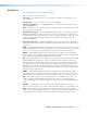
RESET Apply Power Reset LED flashes once, twice, or three times. RESET Release, then immediately press and release again. Reset LED flashes in confirmation. RESET Modes 3, 4, and 5 Press and hold for 3, 6, or 9 seconds. 2 1 RESET Press and hold the Reset button. Release the Reset button. RESET Mode 1 Figure 28. Resetting the SMX ATTENTION: Review the reset modes carefully.
Troubleshooting This section gives recommendations for general checks and actions for problems operating the SMX. 1. Ensure that all devices are plugged in and powered on. The SMX is receiving power if one of the front panel power supply LEDs is lit green. 2. Check to see if one or more outputs are muted. 3. Ensure that an active input is selected for output on the SMX. 4. Ensure that the proper signal format is supplied. 5. Check the cabling and make corrections as necessary. 6.
SIS Configuration and Control The SMX can be configured and operated using the Extron Simple Instruction Set (SIS) of commands. SIS commands can be run from a PC connected to either of the SMX serial ports or the Ethernet port. Use the DataViewer utility or a control system to make serial control the SMX possible. This section describes the SIS command method of communication and control.
Establishing an Ethernet Connection Establish a network connection to the SMX as follows: 1. Open a TCP socket to port 23 using the SMX IP address. NOTE: If the local system administrators have not changed the value, the factory-specificed default, 192.168.254.254, is the correct value for this field. The SMX responds with a copyright message including the date, the name of the product, firmware version, part number, and the current date/time (see Switcher-Initiated Messages on page 36).
SIS Programming Guide Host-to-SMX and SMX-to-Host Communications SIS commands consist of one or more characters per field. No special characters are required to begin or end a command sequence. When the SMX determines that a command is valid, it executes the command and sends a response to the host device. All responses from the switcher to the host end with a carriage return and a line feed (CR/ LF = ]), which signals the end of the response character string. A string is one or more characters.
ppOutnn Volxx] The SMX initiates the Vol message when a front panel output audio volume change has occurred. “pp” is the plane address, “nn” is the output number, and “xx” is the volume level. ppVmtnn*x] The SMX initiates the Vmt message when a video output mute is toggled on or off from the front panel. “pp” is the plane address, “nn” is the output number, and “x” is the mute status: 1 = on, 0 = off.
Symbol Definitions ] = Carriage return and line feed ¦ or = Carriage return with no line feed } • = Space E = Escape key or W NOTE: Input and output numbers in commands may be entered as either 1, 2, or 3-digit numbers. All input and output numbers are reported as 2-digit numbers in the response (for example, 03 for input 3).
X1^ = HDCP compliance 0 = no source connected 1 = source is HDCP compliant 2 = source is not HDCP compliant X1& = Executive mode 0 = enable (basic and admin) 1 = disabled front panel 2 = enabled (basic only) X1* = Reclocker rates for SDI/HD-SDI 00 = auto detect (default) 01 = bypass reclocker X1( = Signal status 0= 1= 2= 3= X2) = Output connection status 0 = no active connection on A or B 1 = first (A) port connected and second boards no signal at the input signal at the input (H) signal at the i
X3! = Slot information (X) Board Type XYZ X = board type (B – Y) YZ = board size (00 – 15) (X) Board Type B Video N DVI Pro C S-video O HDMI D S-video P FOMX 1616 E Wideband Q FOMX 88 F S-video DIN R Reserved G VGA S Reserved H VGA T Reserved I Audio analog U USB J SDI/HDSDI V Reserved K Sync W DVI (2 data blocks) L DVI X No board installed M DVI Y DVI (2 data blocks) (YZ) Reference # Board Size Note 15 16x16 09 8x4x2 For S-video BNC 08 8x8x2 Fo
EDID Minder Table — DDC Source Selection SIS value X3@ Resolution 1 Refresh (Hz) DVI-Pro and HDMI* SIS value X3@ Resolution Refresh (Hz) Resolution Refresh (Hz) Output 1 21 1280x1024 60 2 Output 2 22 1280x1024 75 3 Output 3 23 1365x768 60 4 Output 4 24 1365x768 75 5 Output 5 25 1366x768 60 6 Output 6 26 1366x768 75 7 Output 7 27 1400x1050 60 8 Output 8 28 1600x1200 60 9 640x480 60 29 480p 60 480p 2 channel audio 60 10 640x480 75 30 576p 50 576p
Command and Response Table for SIS Commands Command ASCII Command (Host to Switcher) Response (Switcher to Host) Additional Description Output Switching by Plane NOTES: • • • • • The & tie command for RGBHV and the % tie command for video can be used interchangeably. The ! tie command can be used for switching both video signals and audio signals with the same plane address. The & tie command for RGB and the % tie command for video can be used interchangeably.
Command ASCII Command Response (Host to Switcher) (Switcher to Host) Additional Description View Ties NOTE: If the view follow-all tie command (!) is used for an output with a break-away tie, the SMX will respond with an error message (E14). View RGBHV output tie View video output tie View audio output tie X2@*X# & X@] View RGBHV input tied to output X# on plane X2@.
Command ASCII Command (Host to Switcher) Response Additional Description (Switcher to Host) Global Presets (All Planes) Save current ties as a global preset X1!, Spr X1!] Save the current set of ties as global preset X1!. Recall a global preset X1!. Rpr X1!] Make the global preset X1! the current configuration. NOTE: Attempting to recall an unsaved preset will result in a E11 error code.
Command ASCII Command (Host to Switcher) Response Additional Description (Switcher to Host) Front Panel Lockout (Executive Mode) Lock front panel (advanced functions) 2X Exe2] Enable lock mode 2. Lock front panel 1X Exe1] Enable lock mode 1. Unlock front panel 0X Exe0] Disable lock mode. View front panel lock X X1&] Show lock mode status. NOTE: For full lock mode details, see Setting the Front Panel Locks (Executive Modes) on page 25.
Command ASCII Command Response Query system status S Query specific system status nS X2$ • X2$ • X2$ • X2% • X2^ • X2^ • X3# • X3$] X2$ or X2% or X2^ or X3#] Stsn*X2$ or X2% or X2^ or X3#] Verbose mode 2 or 3 Sts0* 3.31 4.98 24.22 +100.40 03305 03308 1 0 ] Example: (Host to switcher) S (Switcher to host) Additional Description 3.31 and 4.98 are power supply voltages; 24.22 is fan voltage, 100.
Command Query part number and slot information ASCII Command Response Additional Description (Host to Switcher) (Switcher to Host) N 60-xxx-yy *N 60-xxx-yy.X3! n1 X3! n2 X3! n3... X3! n6/8/10] Pno 60-xxx-yy.X3! n1 X3! n2 X3! n3... X3! n6/8/10] Verbose mode 2 or 3 Example: *N Pno60-857-01.L04J07G00G00G00G15D00D15C00C15 Where X3!nx = XYZ; X = type of board (B-T & X), YZ = board size (00-15) and nx is the number of the slot the board is installed in. NOTE: Left table gives X value.
Command ASCII Command Response (Host to Switcher) Additional Description (Switcher to Host) EDID Commands by Slots Assign EDID data to input Assign EDID data to all inputs Save output 1 EDID data View EDID data assignment Export EDID file data Import EDID file data E A X3)*X!*X3@ EDID} E A X3)*X3@*EDID} E S X3)*X3@ EDID} E A X3)*X! EDID} X3) EdidA X!*X3@] X3) EdidA00*X3@] X3) EdidS X3@] X3@] X3) EdidA X!*X3@] E E X3)*X3@ EDID} X6)] X3) EdidE X3@*X6)] E I X3)*X3@ EDID}X6) X3) EdidI X3@] Applies only
Command ASCII Command (Host to Switcher) Response (Switcher to Host) Additional Description Commands Specific to SMX SDI/HD-SDI Boards Output Re-clocking Per Slot Set output reclocker per slot Read reclocker X3)*X#*X1* = X3)*X# = Rte X3)*X#*X1*] X1*] List DSVP (Digital Sync Validation Processing) DSVP for VGA and RGBHV List individual sync (DVSP) X3)*X! LS X1% H,X1% V] X3) FRQ X!1,X1% H,X1% V] Listed as Horizontal, Vertical. Verbose mode 2 or 3 NOTE: Unit responds 0000.00, 0000.
Command ASCII Command Response Additional Description E I X3)*X! HDCP} X1^] X3) HdcpI X!*X1^] View HDCP of input X!. View HDCP of output X#. Verbose mode 2 or 3 (Host to Switcher) (Switcher to Host) HDCP Detect View input HDCP Verbose mode 2 or 3 View output HDCP E O X3)*X# HDCP} X1^] X3) HdcpO X#*X1^] View all inputs HDCP E I X3)*HDCP} View all outputs HDCP E O X3)*HDCP} View HDCP of all inputs in slot X3). X1^1 X1^2 X1^3... X1^n] X3) HdcpI00*X1^1 X1^2...
Command Write input name (per plane) Read input name Write output name (per plane) Read output name ASCII Command Response Additional Description EX2@*X!,nameNI} EX2@*X! NI} EX2@*X#,nameNO} EX2@*X# NO} X2@ Nmi X!,name] name] X2@ Nmo X#,name] name] Assign a name to input X!. (Host to Switcher) (Switcher to Host) Assign a name to output X#. NOTES: • If a preset (global or plane) is unassigned, its name is displayed [unassigned].
Command ASCII Command (Host to Switcher) Response Additional Description X3) UsbcE0*X(] Enable or disable port emulation for all outputs.
Using the Command/Response Table for IP SIS Commands The Command and Response Table begins on page 42. Symbol Definitions X5! = Specific port number 01 – 99 00 = reserved The port number is represented as two ASCII characters (for example, port 05 would be represented as 30 35 in hex). X5@ = GMT offset –12.0 - +14.0 X5# = On/Off status 0 = off or disabled 1 = on or enabled X5$ = Unit name Text string up to 24 characters (A-Z, 0-9, and "-"). Not case sensitive.
X6# = Verbose mode 0 = clear/none (default for Telnet connections) 1 = verbose mode (default for RS-232 and RS-422 connections) 2 = tagged responses for queries 3 = verbose mode and tagged for queries X6^ = Baud rate X6& = Parity 9600 (default), 9200, 38400, 115200 O E N M S = odd = even = none = mark = space X6* = Data bits X6( = Stop bits X7) = Port type 7, 8 X7# = Web page priority flag 0 = internal (default factory reset) 1 = user X7$ = Password 12 digits, alphanumeric User or admin 1, 2 0
X8@ = E-mail account X8# = Notification selection 1 65 - 72 X8$ = Notification selection 2 If X8# = I, then X8$ = 00 (all inputs, or 1 - 16) I = inputs F = fans P = power supply If X8# = F, then X8$ = 00 (both fans), or 01 (fan 1), or 02 (fan 2) If X8# = P, then X8$ = 00 (both power supplies), or 01 (PS 1), or 02 (PS 2) X8% = Notify what? 0= 1= 2= 3= 4= 5= X8& = Default name Combination of the model name and the last three pairs of the MAC address; for example, IPL-T-S2-00-02-3D.
Command and Response Table for IP SIS Commands Command ASCII Command Response EX5$ CN} E • CN} Ipn • X5$] E CN} EX5% CT} X5$] or X5(] Ipt • X5%] E CT} EX5@ CZ} X5%] Ipz X5@] (Host to Switcher) (Switcher to Host) Additional Description IP Setup Commands Set unit name Reset unit name to factory default Read unit name Set time and date Read time and date Set GMT offset Ipn • X5(] See X5% Symbol Definitions on page 53 for more details.
Command ASCII Command Response Set subnet mask EX6) CS} E CS} EX5^ CG} E CG} EX7$ CA} E CA} E • CA} Ips • X6)] EX7$ CU} E CU} E • CU} EX6#CV} Ipu • X7$] Read subnet mask Set gateway IP address Read gateway IP address Set administrator password Read administrator password Reset (clear) administrator password Set user password Read user password Reset (clear) user password Set verbose mode (Host to Switcher) (Switcher to Host) X6)] Ipg • X5^] X5^] Ipa • X7$] X7$] Ipa • X7$] X7$] Ipu • X7$] Vrb X6#
Command ASCII Command Set e-mail recipient EX8@,X8! CR} Ipr X8@,X8!,] Sets e-mail address to account X8@. EX8@ CR} X8!,] Read e-mail address of account X8@. EX8#X8@,X9),X8$,X8% EM} X9) Ipe X8#,X8@*X8$*X8%... X8%] E I65,02,00,2EM} 02IpeI65*00*2222222222222222 ] EX8#X8@,X9),X8$ EM} X8% X8% X8%...
SMX Control Software The Windows-based Extron SMX Control Program, which communicates with the SMX via the RS232/RS422 port and the Ethernet port, provides an easy way to set up ties and sets of ties. The program is compatible with Windows 2000, Windows XP or later. Updates can be downloaded from the Extron website (www.extron.com).
2. Click the Software tab. 3. Scroll to the SMX Control Program and click Install. 4. Follow the on-screen instructions. The installation program creates a C:\Program Files\Extron\SMX folder. Within this folder are created three icons for the SMX Control pgm, SMX Help, Uninstall SMX Control pgm. Starting the Program 1. Click Start > Programs > Extron Electronics > SMX Control Program > SMX Control Pgm (or select the desktop icon, if created during installation). The Comm Port Selection window appears. 2.
• If you select a comm port, click OK and proceed to the Using the Program section on page 62. • If you selected IP [LAN], click OK and proceed to step 3. • If you selected Emulate, click OK and proceed to the Using Emulation Mode section on page 61. 3. If you selected IP [LAN] in step 2, the IP Connection window opens. Set up the connection as follows: a. The Matrix IP Address field defaults to the last IP address entered. A drop-down list to the right contains the most recently used IP addresses.
4. Select the file name under which you want to save any changes to the file and click OK. The SMX Physical Configuration [Emulation Mode] window appears. 5. Select the signal type boards, board sizes, plane addresses, and matrix model for which you are preparing a configuration and click Take. 6. The SMX Control Program window opens (see Using the Program below). Using the Program At startup, the SMX Control Program window appears (see figure 30).
Each tab is selectable and highlights when selected (see figure 31 for an example of audio inputs and outputs on plane 1). Figure 31. Audio Inputs and Outputs on Plane 1 — No Ties Across the top of the main window is the menu bar, and at the right edge of the window, various selectable buttons are available, depending on the current configuration. NOTE: Depending on the particular SMX configuration, some menus, submenus, and buttons may appear grayed out and are not selectable.
• Restore Matrix settings from... — Select this option to restore saved matrix settings files (*.mtx) and overwrite the current settings. NOTE: All current settings (ties, presets, virtual plane, and audio settings) unless already saved, are replaced. • Save This-Session’s settings — Select this option to save the specific session settings (ties, presets, rooms, and audio settings) to file (*.ini), which can be used for restoring those settings later. NOTE: The last saved settings within the same *.
• Assign Device Icons — Select this option to add specific device icons to the main window input and output boxes. This opens a new window showing input and output device icons. Drag and drop an icon onto the applicable input or output boxes. NOTE: Alternatively, clicking on either input or output boxes opens the relevant icon window. Drag and drop an icon onto the boxes. • Edit Device Palette — Selecting this option opens the Editor window (see figure 34).
• Audio-Input Gain settings — Select this to change the audio gain (0.5 dB steps) for all or single inputs. To change the gain, pick an input (or All) and use the adjustment arrows to raise or lower the gain. NOTE: Click on the applicable Changes radio buttons to have any changes either immediate or verifiable. Verify (default setting) accepts changes after the Take button is pressed. Immediate accepts changes instantly. The Take button is removed. • • Click Take (if visible) to accept the changes.
• EDID settings — Select this option to set the EDID settings for selected inputs, and to save the output to any of four user defined outputs. Select Advanced Info to view the EDID data for any selected output (see the above right side image), and to save a record to a user defined ID (User 1-4).
• Update Firmware... — Select this option to update the SMX with the latest firmware. Before using this command, download the latest firmware version from the Extron website (www.extron.com): 1. On the Extron Web page, select the Download tab. 2. Click the Firmware link on the left sidebar menu. 3. Click on “S,” scroll to SMX Multi Matrix switcher, and then click Download. 4. Fill in the required information, then click Download product name_firmware version.exe. 5.
To change the IP settings complete the applicable fields or check the User DHCP box to automatically obtain an IP address. The Take button appears and the Close button changes to Cancel. Click Take to accept the changes or Cancel to reset the fields to the previous settings. Click Close to close the window. NOTE: Fields that appear grayed out are not changeable. To change the date and time settings, complete the applicable fields or click the Sync time to PC button.
To select a file from the server list, click Pick Files to Load to Server, then click Get Selected Files... or Delete Selected Files... as desired. Click Update to refresh file list. • • Hardware status — Select this option from the Tools menu to check status of various hardware components, view serial port configuration, and view firmware details. • Click Update to refresh the window with real time information. • Click Close to exit the window.
• Virtualize... — Select this option to view and set up to 10 virtual planes. Select a Virtual Plane check box then select the desired Physical Planes check boxes. Select Take. New tabs for the virtual planes (planes 1 and 5 in the example below) appear on the inputs page. This recreates configurations from current boards and configurations onto virtual planes. • Name Presets — Select this to assign or edit preset names.
Click Cancel Chgs if you want to cancel pending changes and restore the previous settings. To set all audio inputs to the same gain level, use the All arrows to select the required level. Preferences This drop-down list (see figure 35) includes the following selectable items: Immediate Changes, Hold/Verify Changes, Ties as Lines, Ties as Crosspoints, Frequency-read options, Icons in I/O boxes, Numbers in I/O Boxes, and Catch FPC/other’s Changes.
• Ties as Lines — Selecting this option displays input to output ties as lines. • Ties as Crosspoints — Selecting this option displays input-to-output ties as points. The crosspoints diagram is shown as a matrix with ties that have been made indicated by green boxes. Pending ties that will be made after the Take button is clicked appear as a + while ties that will be broken appear as a - in the Crosspoint box.
Master-Reset Select this menu only if a master reset to factory defaults is desired. It opens a warning window stating the consequences of this action. Click No if the reset is not required. Click Yes to proceed and complete the reset. Help This menu gives access to the SMX Control Program help file, and displays limited SMX configuration information. Figure 36. Help Menu Select Contents to view a help file that can orient you through the various menus and commands.
Select About this Program to see the software version number. Click OK to close the pop-up window. Customizing the SMX Window In the SMX window, the inputs and outputs are represented by boxes. Customize the control program view by assigning device icons that represent the connected devices to each input and output box. 1. Click on an input or an output box. The Input Devices or Output Devices window opens, containing icons representing various types of devices that may be connected to the SMX. 2.
4. When you are finished assigning icons, click OK to close the device window. To change an icon in an input or output box, drag the new icon to the box. The previous icon is replaced. To remove the icon and leave the box empty, drag an empty square from the Devices window to the box. Alternatively, you can display the input and output numbers in the boxes. To do this, select Numbers in I/O Boxes from the Preferences menu.
To remove a tie Drag the output box outline to its tied input box or to the trashcan. • If Hold/Verify Changes has been selected from the Preferences menu, the solid tie line becomes broken. NOTE: If you want to reinstate the tie, click Cancel. The line becomes solid. Click Take to remove the tie. The broken tie line disappears. • If Immediate Changes has been selected from the Preferences menu, the tie is removed immediately.
Figure 40. IP Setting/Options Window NOTES: • Editing the following fields in the IP Settings/Options window while the SMX is connected via the Ethernet port can immediately disconnect the computer from the unit: • Matrix IP Address, Gateway Address, Subnet Mask, Use DHCP, Administrator Password.
3. Press the key on the keyboard or click in another field to exit the Matrix IP Address field. 4. Click the Take button to make the address change take effect. NOTE: Editing the IP Address field while the SMX is connected via Ethernet will immediately disconnect your from the SMX. It is recommended that you connect via RS-232 or RS-422 to edit this field.
Enabling and disabling DHCP Selecting the Use DHCP check box directs the SMX to ignore any entered IP addresses and to obtain its IP address from a Dynamic Host Configuration Protocol (DHCP) server (if the network is DHCP capable). Contact the local system administrator for information about DHCP on your system. ATTENTION: Selecting or deselecting this check box while the SMX is connected via Ethernet can immediately disconnect your PC from the unit.
Enabling daylight saving time When daylight savings time is enabled, the switcher updates its internal clock between daylight saving time and standard time in the spring and fall on the date that the time change occurs in your location. When daylight saving time is turned off, the SMX does not adjust its time reference. Select the Use Daylight Saving check box to enable daylight saving time.
Setting the mail server IP address The Mail Server IP Address field displays the IP address of the mail server that handles the e-mail for the facility in which the SMX switcher is installed. Valid IP addresses consist of four 1-, 2-, or 3-digit numeric subfields separated by dots (periods). Each field can be numbered from 000 through 255. Leading zeros, up to 3 digits total per field, are optional. Values of 256 and above are invalid. Edit this field as follows: 1.
4. Use the check boxes associated with each addressee to select the options about which the addressee will be e-mailed: missing inputs or power supply. 5. When you select either a radio button or a check box for an addressee, the floating box that contains the input numbers is displayed on the Input Settings/Options screen. Select the inputs that need monitoring by clicking on their numbers in this box. Selected input numbers are displayed in white on a gray field.
3. From the Tools menu, select Update Firmware.... The Select Files window opens (see figure 42). Figure 42. Select Files Window with Firmware File Selected 4. Navigate to the folder where you saved the firmware file. Select the file. ATTENTION: Valid firmware files must have the file extension .S19. Any other file extension is not a firmware upgrade and could cause the SMX to cease functioning. NOTE: The original factory-installed firmware is permanently available on the SMX.
Uploading HTML files You can create customized HTML pages for the SMX to display. The HTML Files List window (see figure 43) provides a way to view the contents of the SMX file system and to upload custom HTML pages to the SMX. Figure 43. HTML Files List Window Upload HTML pages as follows: NOTES: • The files listed in the figure 43 are shown for example only and may not be present on your switcher. • The HTML Files List window is for inserting your own HTML pages.
Windows buttons, menus, and trashcan The buttons, drop-down lists, and trash can on the right side of the program window perform the following functions: Power — This button is unavailable for SMX switchers, because the SMX cannot be powered on and off via software. Executive Mode — Locks out front panel operations, except for the viewonly mode functions. Presets menu — Displays a list of up to 32 global presets and up to 10 plane presets.
HTML Configuration and Control The SMX can be configured and controlled through its Ethernet port, connected through a LAN or WAN and accessed with a Web browser such as Microsoft Internet Explorer. The browser displays the factory-installed Web pages, which provide an alternative means of viewing and controlling the SMX.
4. Press the key. The SMX checks to see if it is password-protected. If the SMX is not password-protected, the System Status Web page is displayed. If the SMX is password-protected, the network password dialog box is displayed (see figure 45). 5. In the Password field, enter the appropriate administrator or user password. If desired, select the check box to have the system input the password the next time you enter the SMX IP address. Click OK. Figure 45.
System Status Pages The System Status pages give access to sub-pages: System Status (the default page), Physical Configuration, and DVSP and HDCP. To view each individual page, click on the links in the sidebar menu. System Status The System Status (see figure 47) page has the following sections: System Information (such as unit name and model), Power Status, and Serial Port Settings. This read-only page updates itself periodically to reflect the latest status of the switcher components.
Physical Configuration The Physical Configuration read-only page lists the currently installed boards for the SMX system, showing the size and the total slots of that frame. For each slot, it shows the installed board function or type, board size, and the plane address allocated to that board (see figure 48). Figure 48. Physical Configuration Page DSVP The Digital Sync Validation Processing (DSVP) page displays the current signal status and source of connected video inputs per board.
Configuration Pages The Configuration pages allow system settings (IP address, date/time etc.), passwords (Admin and User), and E-mail settings (mail addresses) to be configured as desired. Additionally, the current firmware can be upgraded by selecting the Firmware Upgrade link. System Settings Page The SMX displays the System Settings page (see figure 50) after selecting the Configuration tab.
IP Settings Fields The IP Settings section provides a location for viewing and editing settings unique to the Ethernet interface. After editing any of the settings on this page, click the Submit button at the bottom of the IP Settings section (see figure 51). a b c d e f g h i Figure 51. IP Settings Fields a Unit Name field — The Unit Name field contains the name used as the “from” information when the SMX E-mails notification of its failed or repaired status.
Date/Time Settings fields The Date/Time Settings section (see figure 52) provides a location for viewing and setting the time functions. Figure 52. Date/Time Settings Fields Change the date and time settings as follows: 1. Click the drop-down box for the desired variable. The adjustable variables are month, day, year, hours, minutes, am/pm, and (time) zone (see figure 52). 2. Click the scroll up or down buttons until the desired variable is visible. 3. Click on the desired variable.
Passwords Page Access the Passwords page (see figure 53) by clicking the Passwords link on the sidebar menu on System Settings page. Figure 53. Passwords Page The fields on the Passwords page are for entering and verifying administrator and user passwords. Passwords are case sensitive and are limited to 12 upper- and lowercase alphanumeric characters. Each password must be entered twice—once in the Password field and then again in the Re-enter Password field to the right.
a Mail IP Address field — The Mail IP Address field displays the IP address of the mail server that handles the e-mail for the facility. Valid IP addresses consist of four 1-, 2-, or 3-digit numeric subfields separated by dots (periods). Each field can be numbered from 000 through 255. Leading zeroes, up to 3 digits total per field, are optional. Values of 256 and above are invalid. b Domain Name field — The Domain Name field displays the domain name that the SMX uses to log on to the e-mail server.
Figure 55. Email Options Menu on the Email Settings Page The Suspend option is useful for temporarily removing personnel from the e-mail list when they are unavailable, such as traveling or vacation. Deleting an e-mail addressee and clicking the Save button removes the recipient from e-mail notification completely.
ATTENTION: Valid firmware files must have the file extension “.S19.” Any other file extension is not a firmware upgrade and could cause the SMX to cease functioning. NOTE: The original factory-installed firmware is permanently available on the SMX. If the attempted firmware upload fails for any reason, the SMX reverts to the factory-installed firmware. 7. Click Open. 8. On the Firmware Upgrade page, click the Upload button. While the firmware is uploading, the Upload button changes to Uploading....
Uploading Files Files to be uploaded may only contain valid alphanumeric characters and underscores. NOTE: The following characters are invalid or not recommended in the files names: + ~ , @ = ‘ [ ] { } < > “ ; : | \ ? and space To upload files to the SMX, follow these steps: 1. Click the Browse button to the right of the file name field on the File Management Web Page. 2. Browse to locate the file that you want to upload, and open it.
To set or replace ties 1. Select the desired plane from the drop-down list (see figure 58). NOTE: When you select a plane, only the available adjustment fields show on the screen, according to the output board type installed and addressed. 1 2 3 Figure 58. Control Pages — User Control Page 2. In the Signal Type section, click Video only, Audio only, or Video & Audio, depending on the signal type to be tied.
NOTES: • If a video tie is removed from a video and audio tie, the button turns red (from amber). • If an audio tie is removed from a video and audio tie, the button turns green (from amber). • If a single signal tie (video or audio) is removed, or there is a combined signal (the Video & Audio signal type button is highlighted), the Video Only or Audio Only button turns gray (see figure 58, input 6, output 7). 4. Click Take to make the tie.
To set output volume levels 1. In the Output Adjustments section, click in the desired output volume field. A dropdown list of volume settings (0 to 64) appears (see figure 60, output 6). Figure 60. Drop-down List of Volume Settings 2. Scroll down to the desired level and click. The page refreshes and the device updates to the selected level. NOTE: Alternatively, use the + and – buttons to increase or decrease the level one step at a time.
To mute or unmute a signal 1. In the Signal Type field (see b, figure 58), click Video only, Audio only, or Video & Audio, depending on the signal type to be muted. Figure 61. A/V Mute Button Status 2. In the Output Adjustment section, click Mute to mute the output. The button changes color according to the muted signal (see the Note below and figure 61), and changes to Muted. The page refreshes and the SMX updates with the selection. NOTES: • If the output is muted for audio only, the button is red.
EDID configuration 1. In the Plane section, select the plane that has an EDID-supporting output board installed. 2. In the EDID Configuration section, click the applicable input number and scroll down to the resolution and refresh rate desired (see figure 62, input 7). NOTE: The drop-down list has 41 selections (see the EDID table on page 41). Figure 62. EDID Configuration Settings 3. If using User Assigned 1 - 4, click one of the Save Output 1 User buttons (1-4) as desired.
Presets Page The Presets page allows global and plane presets to be saved to one of 32 locations for global presets, or to one of the 10 locations for plane presets. NOTE: Global presets save and recall configurations for all planes, and plane presets save and recall configurations for a specific plane, not affecting other planes. Saving the current configuration as a global preset 1. In the Global Presets section, click Save Preset. The button changes to Select Preset..., and grays out.
Recalling a global preset To recall a global preset as the current configuration, click the button for the desired preset in the Global Presets section. Saving the current configuration as a plane preset 1. In the Plane Preset section, click the plane drop-down list, and select the relevant plane. 2. Click Save Preset. The button changes to Select Preset..., and grays out. NOTE: All unassigned buttons become active. The global preset field grays out. 3.
Ethernet Control This section describes Ethernet connection and Telnet communication to the SMX and includes: • Ethernet Link • Subnetting — A Primer ACT LAN The rear panel Ethernet connector on the SMX can be connected to an Ethernet LAN or WAN. This connection makes SIS control of the SMX possible using a computer connected to the same network.
Ping to determine Extron IP address The ping utility is available at the command prompt. Ping tests the Ethernet interface between the computer and the SMX. Ping can also be used to determine the actual numeric IP address from an alias and to determine the web address. Ping the SMX as follows: 1. From the Windows Start menu, select All Programs > Accessories > Command Prompt. The Command Prompt window opens. NOTES: The command prompt can also be accessed from the Run... field.
If you use a web browser or Telnet the first time you connect a PC to an SMX via IP, you may need to temporarily change the IP settings of the PC in order to communicate with the switcher. Then you must change the switcher default settings (IP address, subnet mask, and [optional] administrator name and password) in order to use the unit on an intranet (LAN) or on the Internet. After you have set up the SMX for network communication, you can reset the PC to its original network configuration.
5. Execute a ping command by entering ping followed by a space and the new IP address at the command prompt. For example: ping 10.13.197.7 You must ping the SMX in order for the IP address change to take place. The response should show the new IP address, as shown in the following picture. Figure 66. Ping Command To verify that the update was successful, reconnect using either Telnet or a Web browser. 6. After verifying that the IP address change was successful, enter the arp -d command at the DOS prompt.
Telnet tips It is not the intention of this guide to detail all of the operations and functionality of Telnet; however, some basic level of understanding is necessary for operating the SMX through Telnet. Connecting to the SMX (Open command) Connect to the SMX using the Open command. Once your computer is connected to the SMX, you can enter the SIS commands the same as you would if you were using the RS-232 link. Connect to the SMX as follows: 1. At the Telnet prompt, enter open .
Setting carriage return line feed Unless commanded otherwise, Telnet transmits a line feed character only (no carriage return) to the connected switcher when the key is pressed. This is the correct setting for SIS communication with the SMX. The Telnet set crlf command forces Telnet to transmit carriage return and line feed characters when is pressed; however, if crlf is set, the SIS link with the switcher does not function properly.
Subnet Masks and Octets The subnet mask (see figure 69) is used to determine whether the local and remote devices are on the same or different subnet. The subnet mask consists of four numeric octets separated by dots. Each octet can be numbered from 000 through 255, up to 3 digits total per octet. Leading zeros are optional. The octets determine whether or not the same octets of two IP addresses will be compared when determining if two devices are on the same subnet.
Reference Information This section identifies part numbers for related products, describes mounting procedures, and button label customizing. This section includes: • Mounting the Switcher • Button Labels • Button Label Blanks Mounting the Switcher NOTE: The SMX comes in 2U, 3U, 4U, or 5U sizes. Before attempting installation, ensure the rack is able to accommodate your particular device size.
Rack Mounting To rack mount the SMX, use two screws on each end of the switcher to attach it to the rack (see figure 71). Figure 71. Mounting the SMX Button Labels Page 119 provides strips of blank button labels. If desired, photocopy them or cut them out of the guide, write button information in each button area as desired, and put them in the SMX input or output buttons windows. Labels can be created using the Extron Button-Label Generator software.
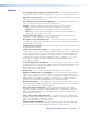
Figure 72. Button Label Generator Window 2. From the Systems drop-down list, select a system button configuration. The Matrix Switchers 3232 or 1616 selections most closely match the button configuration of the SMX (the SMX option gives you four rows of blank buttons). However, you can select any option from this menu. Selecting Customize Button Layouts opens a blank worksheet on which customized buttons can be placed in any desired configuration. 3.
Replacing Button Labels The button caps are pre-labeled for your convenience. However, you can change them with the included button labels. The button assembly consists of a clear lens cap, the button label, and a white diffuser (see figure 73). Remove the button assembly from the SMX as follows: 1. Make new labels using either the blanks on page 119 or the Button Label Generator software. Cut the labels out. 2.
Button Label Blanks SMX System MultiMatrix Switcher • Reference Information 117
Extron Warranty Extron Electronics warrants this product against defects in materials and workmanship for a period of three years from the date of purchase.