
User guide


SMX System MultiMatrix Switcher • Installation and Cabling 9
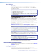
f SMX 44 FOX 4G MM — Connect fiber optic input cables from a signal source to input
ports and from output ports to a suitable display. LEDs light when signals are present.
1
2
3
4
FIBER OPTIC
OUT
IN
OUT
IN
OUT
IN
OUT
IN
ADDRESS
5
6
7
8
FIBER OPTIC
OUT
IN
OUT
IN
OUT
IN
OUT
IN
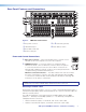
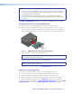
g SMX 88 HD-SDI — Connect SDI, HD-SDI, or dual link HD-SDI input sources to any
of the BNC input connectors. Connect suitable display devices to the BNC output
connectors.
SDI / HDSDI OUTPUTS
SDI / HDSDI INPUTS
8
7
14
5
6
3
2
8
7
14
5
6
3
2
8
7
14
5
6
3
2
DIGITAL VIDEO
ADDRESS
NOTE: It is recommended to terminate unused I/Os with 75 ohm terminating
connectors.
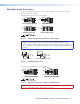
h SMX 88 VGA — Connect high resolution computer-video rate input sources to any of
the 15-pin HD female connectors. Connect suitable display devices to the 15-pin HD
output connectors.
COMPUTER IN
5
6
7
8
1
2
3
4
5
6
7
8
1
2
3
4
COMPUTER OUT
ADDRESS
i SMX 88 SV (DIN) and j SMX 84 YC — Connect S-video input sources to any of
the BNC pairs or 4-pin mini DIN input connectors. Connect suitable display devices to
the BNC pairs or 4-pin mini DIN output connectors.
S-VIDEO IN
S-VIDEO OUT
8
7
14
5
6
3
2
8
7
14
5
6
3
2
ADDRESS
S-VIDEO
S-VIDEO IN
S-VIDEO OUT
S-VIDEO
14
3
2
14
3
2
14
3
2
ADDRESS
i
j
k SMX 84 V — Connect composite video input signals to the BNC input connectors.
Connect display devices to the BNC output connectors.
8
7
14
5
6
3
2
14
3
2
VIDEO OUTPUTS
VIDEO INPUTS
ADDRESS
VIDEO
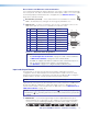
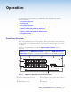
l SMX 88 A — Connect stereo or mono audio input signals to any of the eight sets of
3.5 mm, 5-pole captive screw connectors marked Inputs. Wire the connector for the
appropriate signal type (see Wiring the Audio Connectors on page 12).
ADDRESS
INPUTS
L 1 R
L 2 R
L 3 R
L 4 R
L 5 R
L 6 R
L 7 R
L 8 R
OUTPUTS
L 1 R
L 2 R
L 3 R
L 4 R
L 5 R
L 6 R
L 7 R
L 8 R
Connect audio devices, such as an audio amplifier or powered speakers to the eight
sets of 3.5 mm, 5-pole captive screw connectors marked “Outputs.” The connectors
output the selected unamplified, line level audio (see Wiring the Audio Connectors on
page 12 to properly wire an output connector).
By default, audio and video use different boards, so that audio breakaway is switched
separately. This is done via the front panel, Ethernet, or the RS-232 or RS-422 link,
allowing selection from any of the audio input sources (see Operation on page 13,
SIS Configuration and Control on page 34, SMX Control Software on page 59, or
HTML Control and Configuration on page 87 for control details).
m Plane address rotary switch — This 16 position rotary switch
defines a plane address for up to 16 I/O boards. To set an address,
insert a small screwdriver in the slot and rotate it to the desired
number (0-9, A-F). Each plane address is then identifiable during
SMX control and configuration.
ADDRESS