
Setup guide

MVX Matrix Switchers • Setup Guide
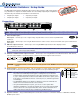
The MVX VGA matrix switchers distribute high resolution video and stereo audio input signals to
any combination of outputs. The matrix switcher can route multiple input/output configurations
simultaneously. The switchers are available in four matrix sizes:
z 4 inputs by 4 outputs z 4 inputs by 8 outputs
z 8 inputs by 4 outputs z 8 inputs by 8 outputs
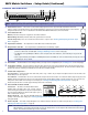
Connections
100-240V 0.3A
50-60Hz
MVX 88 VGA A
RS-232
OUTPUTS
L
R
7
L
R
8
L
R
5
L
R
6
L
R
3
L
R
4
L
R
1
L
R
2
C
U S
LISTED
1T23
I.T.E.
1
2
3
4
INPUTS
5
6
7
8
1
2
3
4
OUTPUTS
3
4
5
6
7
8
5 4
1 2 3
NOTE: Smaller matrix sizes have fewer input connectors, output connectors, or both.
a Video and audio inputs —
1
Video inputs — Connect up to four or eight analog computer-video sources to these 15-pin HD female
connectors.
Audio inputs — Connect up to four or eight unbalanced stereo audio sources to these 3.5 mm mini stereo jacks for unbalanced
audio input.
b RGB video output connectors — Connect up to four or eight RGBHV high resolution video displays to these
15-pin HD female connectors.
NOTE: The MVX switchers can also switch RGBS, RGsB, RsGsBs, component/HDTV video, S-video, and composite video.
Some video sources may require adapters.
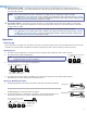
c Balanced or unbalanced audio output connectors — Connect up to four or eight balanced or unbalanced stereo audio devices,
such as an audio amplifier or powered speakers, to these 3.5 mm, 5-pole captive screw connectors.
Ring
Sleeve(s)
Tip
Tip
Ring
Sleeve(s)
Tip
Tip
Unbalanced Stereo Output Balanced Stereo Output
NO GROUND HERE.
NO GROUND HERE.
LR
Do not tin the wires!
CAUTION: For unbalanced audio, connect the sleeves to the ground contact. DO NOT connect the sleeves to the negative (-)
contacts.
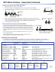
d RS-232 connector — Connect a host device, such as a computer or control system, to the switcher
RS-232 FunctionPin
1
2
3
4
5
6 - 8
9
—
Tx
Rx
—
Gnd
—
—
Not used
Transmit data
Receive data
Not used
Signal ground
Not used
Hardwired IR
via this 9-pin D connector for remote control of the switcher. See the pinout drawing at right.
NOTES: • The cable used to connect the RS-232 port to a computer or control system
may need to be modified by removing pins or cutting wires. If you encounter
problems while operating under RS-232 control (the switcher may hang up), pins
1, 4, 6, 7, and 8 may need to be disconnected. Either cut the wire to pins 1, 4, and
6 through 8 in a hard-shelled connector or remove pins 1, 4, and 6 through 8 from
a molded plug.
• See MVX Matrix Switchers User Guide for definitions of the SIS commands and
details on how to install and use the control software.
• Using the hardwired IR input on pin 9, you can use a control system with
IR-learning capabilities to operate the switcher just as if you were using an IR 501
remote control. The control system must first “learn” the IR command from an
IR 501, after which it sends the same commands to the MVX via pin 9.
e AC power connector — Plug a standard IEC power cord into this connector to connect the switcher to a 100 VAC to 240 VAC,
50-60 Hz power source.