MVX Plus 128 VGA A Computer video (VGA) and Audio Matrix Switcher 68-521-30 Rev.
Precautions Safety Instructions • English Warning This symbol is intended to alert the user of important operating and maintenance (servicing) instructions in the literature provided with the equipment. Power sources • This equipment should be operated only from the power source indicated on the product. This equipment is intended to be used with a main power system with a grounded (neutral) conductor. The third (grounding) pin is a safety feature, do not attempt to bypass or disable it.
FCC Class A Notice N This equipment has been tested and found to comply with the limits for a Class A digital device, pursuant to part 15 of the FCC Rules. These limits are designed to provide reasonable protection against harmful interference when the equipment is operated in a commercial environment. This equipment generates, uses and can radiate radio frequency energy and, if not installed and used in accordance with the instruction manual, may cause harmful interference to radio communications.
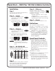
Quick Start — MVX Plus 128 VGA A Matrix Switcher Step 6 — Ethernet Installation If desired, connect a network WAN or LAN hub, a control system, or computer to the Ethernet RJ-45 port. See chapter 2, “Installation”, for details. Step 1 Turn off power to the input and output devices, and disconnect the power cords. • Network connection — Wire as a patch (straight) cable. • Computer or control system connection — Wire the interface cable as a crossover cable. Step 2 — Inputs a.
Quick Start — MVX Plus 128 VGA A Matrix Switcher, continued Esc button cancels selections in progress and resets the front panel button indications. The Esc button does not reset the current configuration, the RGBHV and audio selection, any presets, or any audio level or volume settings. On audio models, Esc increments the level and volume. See “Viewing and adjusting the audio level” in the next column. RGBHV and Audio buttons select/deselect video and/or audio.
Table of Contents Chapter One • Introduction . ..................................................................................................... 1-1 About this Manual ..................................................................................................................... 1-2 About the MVX Plus 128 VGA A Matrix Switcher ................................................... 1-2 Definitions . .......................................................................................................
Table of Contents, cont’d Viewing and adjusting the input audio level ...................................................................... 3-32 Example.10:.Viewing.and.adjus ting.an.input.audio.level............................................... 3-34 Viewing and adjusting the output volume . ........................................................................ 3-36 Reading.the.dis played.volume.......................................................................................... 3-37 Example.11:.
Chapter Five • Matrix Software .............................................................................................. 5-1 Matrix Switchers Control Program .................................................................................. 5-2 Ethernet.protocol.s ettings ................................................................................................... 5-3 Using the Matrix Switcher Control software .........................................................................
Table of Contents, cont’d Chapter 6 • HTML Operation .................................................................................................... 5-25 Download the Startup Page ................................................................................................. 6-2 System Status Page ................................................................................................................... 6-3 DSVP page . ..........................................................................
Appendix A • Ethernet Connection . ................................................................................... A-1 Ethernet Link ................................................................................................................................ A-2 Ethernet connection ................................................................................................................. A-2 Default address ........................................................................................
PRELIMINARY Table of Contents, cont’d 68-521-30 B 04 07 All trademarks mentioned in this manual are the properties of their respective owners.
1 Chapter One Introduction About this Manual About the MVX Plus 128 VGA A Matrix Switcher Definitions Features PRELIMINARY MVX Plus 128 VGA A Matrix Switcher
Introduction About this Manual This manual contains installation, configuration, and operating information for the Extron MVX Plus 128 VGA A 12-input by 8-output wideband computer video (VGA) and audio (A) matrix switcher. About the MVX Plus 128 VGA A Matrix Switcher The MVX matrix switcher distributes any of 12 inputs to any combination of 8 outputs. The matrix switcher can route multiple input/output configurations simultaneously.
The MVX Plus 128 VGA A switcher inputs and outputs VGA video on 15-pin HD connectors and audio on 3.5 mm, 5-pole captive screw terminals. The audio switching can either be linked with the video (audio follow) or be independent of the video (audio breakaway). Adjustable input audio gain and attenuation compensates for level differences between audio inputs.
Introduction, cont’d Features Video — The switcher inputs and outputs RGBHV or RGBS (VGA) video on 15-pin HD connectors. It can also switch RGsB, RsGsBs, component/HDTV, S-video, or composite video. Bandwidth — The MVX Plus 128 VGA A switcher provides a minimum of 300 MHz (-3 dB) video bandwidth, fully loaded. Audio inputs — Input and output stereo audio, balanced or unbalanced, is provided on 3.5 mm, 5-pole captive screw terminals.
Rooming — The switcher can be programmed to group multiple outputs to specific “rooms”, allowing them to have their own presets. • Tie any input to any or all outputs. • Quick multiple tie — Multiple inputs can be switched to multiple outputs simultaneously. This allows all displays (outputs) to change from source to source at the same time. • Audio follow — Audio can be switched with its corresponding video input via front panel control or under Ethernet or serial port remote control.
Introduction, cont’d Global memory presets — Input/output configurations can be stored in any of 32 global memory presets. You can then recall those configurations, when needed, with a few simple steps using the front panel. For the MVX Plus 128 VGA A, 20 global memory presets are available from the front panel; the remaining presets are available via serial port control.
2 Chapter Two Installation Mounting the Switcher Rear Panel Cabling and Views Front Panel Configuration Port PRELIMINARY MVX Plus 128 VGA A Matrix Switcher
Installation Mounting the Switcher UL requirements PRELIMINARY The following Underwriters Laboratories (UL) requirements pertain to the installation of the MVX Plus 128 VGA A into a rack. 1. Elevated operating ambient temperature — If the equipment installed in a closed or multi-unit rack assembly, the operating ambient temperature of the rack environment may be greater than room ambient temperature.
Rear Panel Cabling and Views Figure 2-1 shows the MVX Plus 128 VGA A. 1 2 COMPUTER OUT 7 9 11 1 3 5 7 2 4 6 8 10 12 2 4 6 8 INPUTS 2 3 4 8 5 6 OUTPUTS 7 3 8 9 10 11 12 1 2 3 4 5 6 7 8 REMOTE LISTED 1T23 I.T.E. 1 7 RESET 5 6 LAN 3 RS232/RS422 COMPUTER IN 1 5 4 C Use Electrostatic discharge precautions (be electrically grounded) when making connections. Electrostatic discharge (ESD) can damage equipment, even if you cannot feel, see, or hear it.
Installation, cont’d Audio connections By default, the audio ties follow the video ties. Audio breakaway, which can be activated via the front panel or under Ethernet or serial port control, allows you to select from any one of the audio input sources and route it separately from its corresponding video source. See chapter 3, “Operation”, chapter 4, “Programmer’s Guide”, chapter 5, “Matrix Software”, and chapter 6, “HTML Operation” for details.
d Connections for balanced and unbalanced audio outputs — These 3.5 mm, 5-pole captive screw connectors output the selected unamplified, line level audio. Connect audio devices, such as an audio amplifier or powered speakers. See figure 2-4 to properly wire an output connector. Use the supplied tie-wrap to strap the audio cable to the extended tail of the connector. NO GROUND HERE. Do not tin the wires! Unbalanced Stereo Output Tip Ring Sleeve(s) Tip Ring R Sleeve(s) Tip L Tip NO GROUND HERE.
Installation, cont’d Ethernet connection LAN port — If desired, for IP control of the system, connect the matrix switcher to a PC or to an Ethernet LAN, via this RJ-45 connector. You can use a PC to control the networked switcher with SIS commands from anywhere in the world. You can also control the switcher from a PC that is running Extron’s Windows-based control program or has downloaded HTML pages from the switcher.
Patch (straight) cable Pin Clip Down Pins 1 2 3 4 5 6 7 8 RJ-45 connector 1 White-orange 1 White-orange Orange 2 Orange 3 White-green 3 White-green 4 Blue 4 Blue 5 White-blue 5 White-blue 6 Green 6 Green 7 White-brown 7 White-brown 8 Brown 8 Brown Crossover cable Pin Twisted Pairs 7&8 3&6 4&5 Side 2 Wire color 2 12345678 1&2 Pin Side 1 Wire color Pin Side 2 Wire color 1 White-orange 1 White-green 2 Orange 2 Green 3 White-green 3 White-orange 4 Blue
Installation, cont’d Front Panel Configuration Port CONTROL CONFIG ENTER PRESET I/O ESC VIEW VIDEO AUDIO MVX PLUS SERIES VGA MATRIX SWITCHER WITH IP LINK™ 9 Figure 2-7 — Front panel configuration port i Configuration port — This 2.5 mm mini stereo jack serves the same serial communications function as the rear panel Remote port, but is easier to access than the rear port after the matrix switcher has been installed and cabled. The optional 9-pin D to 2.
3 Chapter Three Operation Front Panel Controls and Indicators Front Panel Operations Rear Panel Operations Optimizing the Audio Troubleshooting Configuration Worksheets PRELIMINARY MVX Plus 128 VGA A Matrix Switcher
Operation Front Panel Controls and Indicators The front panel controls (figure 3-1) are grouped into two sets. The input and output buttons are grouped on the left side of the control panel. The control buttons and video/audio (I/O) selection buttons are grouped on the right side of the panel.
Input and output buttons b Input buttons — The input buttons have two primary functions (•) and five secondary functions (❏): • Select an input. • Identify the selected input. ❏ (Input 1 only) With the Output 1 button, select I/O Group mode. See “I/O grouping” on page 3-19. ❏ Select a preset. See “Using presets” on page 3-26. ❏ Display the RGB delay. See “Setting RGB delay” on page 3-23. ❏ Display the output volume level. See “Viewing and adjusting the output volume” on page 3-36.
Operation, cont’d Control buttons c Enter button — The Enter button has three primary functions (•) and six secondary functions (❏): • Save changes that you make on the front panel. To create a simple configuration: PRELIMINARY d 3-4 Specify RGBHV, audio, or both (see I/O selection buttons [g] and [h]). Press the desired input button (a). Press the desired output button(s) (b). Press the Enter button. • Indicate that a potential tie has been created but not saved.
e View (<) button — The View (<) button has two primary functions (•) and eight secondary functions (❏): • Select View-only mode that displays the current configuration. • Indicate that View-only mode is active. ❏ In the I/O Group mode, select group 3. See “I/O grouping” on page 3-19. ❏ In the I/O Group mode, indicate that group 3 is selected. See “I/O grouping” on page 3-19. ❏ Decrease the RGB delay of switches to the selected output. See “Setting RGB delay” on page 3-23.
Operation, cont’d f Esc (>) button — The Esc (>) button has two primary functions (•) and eight secondary functions (❏): • Cancel operations or selections in progress and reset the front panel button indicators. PRELIMINARY N The Esc (>) button does not reset the current configuration, the RGBHV button and Audio selection button, any presets, or any audio gain or attenuation or volume settings. 3-6 • Flashes once to indicate that the escape function has been activated.
I/O controls You must specify video, audio, or both when you are creating or viewing a configuration. This is done with the RGBHV button (g) and Audio (h) buttons. h RGBHV button — The RGBHV button has two primary functions (•) and six secondary functions (❏): • Selects and deselects video for a configuration that is being created or viewed. • Lights green to indicate that video is available for configuring or for viewing.
Operation, cont’d Button icons The numbered translucent covers on the input and output pushbuttons can be removed and replaced to insert labels behind the covers. Input and output labels can be created easily with Extron’s Button-Label Generator software, which ships with every Extron matrix switcher. Each input and output can be labeled with names, alphanumeric characters, or even color bitmaps for easy and intuitive input and output selection (figure 3-2).
The current configuration and all presets are saved in non-volatile memory. When power is applied, the most recent configuration is retrieved. The previous presets remain intact. If an error occurs during the self-test, the switcher locks up and does not operate. If your switcher locks up on power-up, call the Extron S3 Sales & Technical Support Hotline. Creating a configuration 1.
Operation, cont’d Example 1: Creating a set of video and audio ties In the following example, input 5 is tied to outputs 3, 4, and 8. The steps show the front panel indications that result from your action. N This example assumes that there are no ties in the current configuration. 1. Press and release the Esc button (figure 3-3). Press the Esc button to clear all selections. CONTROL ENTER PRESET VIEW ESC The button flashes once. Figure 3-3 — Clear all selections PRELIMINARY 2.
5. Press and release the Enter button (figure 3-7). Press the Enter button to confirm the configuration change. ENTER All input buttons and output buttons return to unlit or background illumination. The Enter button returns to unlit or background illumination.
Operation, cont’d Example 2: Adding a tie to a set of video and audio ties In the following example, a new video tie is added to the current configuration. The steps show the front panel indications that result from your action. N This example assumes that you have performed example 1. 1. Press and release the Esc button (figure 3-9). Press the Esc button to clear all selections. CONTROL ENTER PRESET VIEW ESC The button flashes once. Figure 3-9 — Clear all selections 2.
5. Press and release the Enter button (figure 3-13). Press the Enter button to confirm the configuration change. ENTER All input buttons and output buttons return to unlit or background illumination. The Enter button returns to unlit or background illumination. Figure 3-13 — Press the Enter button The current configuration (figure 3-14) is now: • Input 5 video is tied to output 1, output 3, output 4, and output 8. • Input 5 audio is tied to output 3, output 4, and output 8.
Operation, cont’d Example 3: Removing a tie from a set of video and audio ties In the following example, an existing audio tie is removed from the current configuration. The steps show the front panel indications that result from your action. N This example assumes that you have performed example 1 and example 2. 1. Press and release the Esc button (figure 3-15). Press the Esc button to clear all selections. CONTROL ENTER PRESET VIEW ESC The button flashes once. Figure 3-15 — Clear all selections 2.
5. Press and release the Enter button (figure 3-19). Press the Enter button to confirm the configuration change. ENTER All input buttons and output buttons return to unlit or background illumination. The Enter button returns to unlit or background illumination. Figure 3-19 — Press the Enter button The current configuration (figure 3-20) is now: • Video — Input 5 video is tied to output 1, output 3, output 4, and output 8. • Audio — Input 5 audio is tied to output 3 and output 8.
Operation, cont’d Viewing a configuration The current configuration can be viewed using the front panel buttons. The View-only mode prevents inadvertent changes to the current configuration. View-only mode also provides a way to mute video and audio outputs (see “Muting and unmuting video and/or audio outputs” on page 3-29. View the current configuration as follows: 1. Press the Esc button to clear any input button indications, output button indications, or control button indications that may be on. 2.
Example 4: Viewing video and audio, audio only, and video only ties The following steps show an example of viewing the video and audio, audio-only, and video-only ties in the current configuration. The steps show the front panel indications that result from your action. N This example assumes that you have performed example 1, example 2, and example 3. 1. Press and release the Esc button (figure 3-21). Press the Esc button to clear all selections. CONTROL ENTER PRESET VIEW ESC The button flashes once.
Operation, cont’d N You can also view a set of ties by selecting a tied output. To demonstrate this, note the number of a lit output button, and then press and release the output button for an untied (unlit or background illumination) output. Observe that all of the untied outputs light. Then press the output button that you noted previously and observe that the selected output button, the tied input button (input 5), and the output buttons light for all of the outputs that are tied to the input. 5.
I/O grouping I/O grouping is a matrix switcher feature that allows you to subdivide the front panel controls of the matrix into four smaller functional sub-switchers and limit tie creation from the front panel only. Inputs and outputs can be assigned to one of four groups or not assigned to any group. When you are creating ties on the front panel, inputs and outputs that are assigned to a group can be tied only to other outputs and inputs within the same group.
Operation, cont’d 3. Press and release one of the Control buttons to select a group: • Press the Enter button to select group 1. • Press the Preset button to select group 2. • Press the View button to select group 3. • Press the Esc button to select group 4. 4. Select the desired input(s) and output(s) to assign to the group by pressing the input and output buttons. 5.
Example 5: Grouping inputs and outputs In the following an example, several switcher inputs and outputs are assigned to groups. The steps show the front panel indications that result from your action. 1. Press and release the Esc button (figure 3-28). Press the Esc button to clear all selections. CONTROL ENTER PRESET VIEW ESC The button flashes once.
Operation, cont’d 4. Press and release the input 1 through 4 and output 1 through 4 buttons (figure 3-31). Press and release the Input 1 through Input 4 buttons. The selected buttons light. INPUTS 1 2 3 4 5 6 7 8 9 Press and release the Output 1 through Output 4 buttons. The selected buttons light. 1 2 3 4 5 6 7 8 OUTPUTS Figure 3-31 — Assign inputs and outputs 5. Press and release the Preset button to select group 2 (figure 3-32). PRELIMINARY Press and release the Preset button to select group 2.
Setting RGB delay The switcher can briefly blank the RGB (video) output while it switches to the new input’s sync source, and then switches the RGB signals. This allows a brief delay for the display to adjust to the selected input’s sync timing before displaying the new picture, which then appears without glitches. RGB delay, also known as Triple-Action Switching or video mute switching, is user selectable from 0 to 5 seconds, in half-second increments.
Operation, cont’d Example 6: Setting the RGB delay for an output In the following example, the RGB delay is increased for output 1. The steps show the front panel indications that result from your action. 1. Press and release the Esc button (figure 3-34). Press the Esc button to clear all selections. CONTROL ENTER PRESET VIEW ESC The button flashes once. Figure 3-34 — Clear all selections 2. Press and hold the RGBHV button for approximately 2 seconds (figure 3-35).
Press and release the Esc (>) button once (figure 3-37) to increase the RGB delay by a half second. 4. Press and release the Esc (>) button twice more to increase the RGB delay by a another full second. Note the input button indication changes that occur each time the Esc (>) button is pressed and released. Figure 3-37 show the result of pressing the Esc (>) button a total of three times.
Operation, cont’d Using presets PRELIMINARY The current configuration (configuration 0) can be saved as a preset in any one of 32 preset memory addresses. Preset locations are assigned to the input buttons and output buttons. Up to 20 presets can be selected from the front panel to be either saved or retrieved. When a preset is retrieved from memory, it becomes the current configuration.
Example 7: Saving a preset In the following example, the current configuration is saved as a preset. The steps show the front panel indications that result from your action. 1. Press and release the Esc button (figure 3-40). Press the Esc button to clear all selections. CONTROL ENTER PRESET VIEW ESC The button flashes once. Figure 3-40 — Clear all selections Press and hold the Preset button for approximately 2 seconds until it blinks (figure 3-41).
Operation, cont’d Example 8: Recalling a preset In the following example, a preset is recalled to become the current configuration. The steps show the front panel indications that result from your action. 1. Press and release the Esc button (figure 3-44). Press the Esc button to clear all selections. CONTROL ENTER PRESET VIEW ESC The button flashes once. Figure 3-44 — Clear all selections 2. Press and release the Preset button (figure 3-45).
Muting and unmuting video and/or audio outputs Individual outputs can be muted or unmuted as follows: 1. Press the Esc button to clear any input button indications, output button indications, or control button indications that may be on. 2. Press and release the View button. 3. Select video, audio, or both to mute or unmute by pressing the RGBHV button and/or the Audio button. 4. One at a time, press and hold the button(s) for the desired output(s) for approximately 2 seconds.
Operation, cont’d 3. To select both video and audio for viewing and muting, if necessary, press and release the RGBHV button and the Audio button (figure 3-49). N This example shows the front panel indications if example 1, example 2, and example 3 have been completed. I/O VIDEO Press the RGBHV/ Video button to toggle on and off. The button lights green when selected. AUDIO Press the Audio button to toggle on and off. The button lights red when selected.
5. One at a time, press and hold the Output 3 button and then the Output 4 buttons (figure 3-51) for approximately 2 seconds until each button lights steadily. The output 3 and output 4 video and audio signals are unmuted. Mute outputs one at a time. 3 2 seconds 3 Press and hold the Output 3 button. The button lights amber to indicate that the RGBHV and audio outputs are not muted. 4 2 seconds 4 Press and hold the Output 4 button.
Operation, cont’d Viewing and adjusting the input audio level The audio level of each input can be displayed and adjusted through a range of -18 dB to +24 dB to ensure that there is no noticeable volume difference among sources (figure 3-53). The audio level can be adjusted from the front panel or under serial port or Ethernet control. The default audio level is 0 dB.
Input audio level adjustment displays MVX Plus 128 VGA A dB 24 1 2 3 4 5 6 7 8 23 1 2 3 4 5 6 7 8 F 23 22 1 2 3 4 5 6 7 8 S 22 21 1 2 3 4 5 6 7 8 21 20 1 2 3 4 5 6 7F 8 20 19 1 2 3 4 5 6 7S 8 19 18 1 2 3 4 5 6 7 8 18 17 1 2 3 4 5 6F 7 8 17 16 1 2 3 4 5 6S 7 8 16 15 1 2 3 4 5 6 7 8 15 14 1 2 3 4 5F 6 7 8 14 13 1 2 3 4 5S 6 7 8 13 12 1 2 3 4 5 6 7 8 12 11 1 2 3 4F 5 6 7 8 11 10
Operation, cont’d Example 10: Viewing and adjusting an input audio level In the following example, an audio level is viewed and adjusted. The steps show the front panel indications that result from your action. 1. Press and release the Esc button (figure 3-54). Press the Esc button to clear all selections. CONTROL ENTER PRESET VIEW ESC The button flashes once. Figure 3-54 — Clear all selections 2. Press and hold the Audio button for approximately 2 seconds (figure 3-55).
4. Press and release the View (<) button once (figure 3-57) to decrease the input audio level by 1 dB. Press and release the View (<) button several more times (figure 3-57) to decrease the input audio level by 1 dB per button press. Note the output button indication changes that occur each time the View (<) button is pressed. Figure 3-59 shows the result of pressing the View (<) button a total of nine times. Note that the level is now displayed in red to indicate a negative level.
Operation, cont’d Viewing and adjusting the output volume The audio level of each output can be displayed and adjusted through a range of 100% (no attenuation) to 0% (maximum [85 dB] attenuation). The audio level can be adjusted from the front panel or under RS-232/RS-422 or Ethernet control. The default volume is 100% (no attenuation). N Output volume is protected when front panel Lock mode 2 is selected. You can view the volume in Lock mode 2 but you cannot adjust it from the front panel. 1.
Reading the displayed volume N This section is a detailed look at reading the output volume display on the switcher’s front panel. If you do not need to read the exact value of the volume setting, skip this section. There are 65 steps of volume attenuation, with 1 dB per step (button push), except for 0-to-1, which is 22 dB. At maximum attenuation, no input buttons are lit, 85 dB of attenuation is applied, and the audio output is effectively muted.
Operation, cont’d Audio volume adjustment settings Highest Highest dB of Output number input dB of Output number input attenuation volume attenuation volume button lit button lit None 0% 85 Fast 6 63 5.5% 31 53.5% Slow blink 1 blink 6 62 7% 30 55% 1 Fast blink 1 8.5% 60 10% 59 11.5% 2 Slow blink 58 13% 57 14.5% Fast blink 56 16% 2 55 17.5% 54 19% 53 20.5% 52 22% 51 23.
Example 11: Viewing and adjusting an output volume level In the following example, the audio output volume is viewed and adjusted. The steps show the front panel indications that result from your action. 1. Press and release the Esc button (figure 3-59). Press the Esc button to clear all selections. CONTROL ENTER PRESET VIEW ESC The button flashes once. Figure 3-59 — Clear all selections 2. Press and hold the Audio button for approximately 2 seconds (figure 3-60).
Operation, cont’d N Volume is protected when front panel Lock mode 2 is selected. You can view the volume in Lock mode 2 but you cannot change it from the front panel. If front panel Lock mode 2 is selected and you try to perform step 4, the actions are ignored and the Enter, RGBHV, and Audio buttons flash. 4. Press and release the Esc (>) button once (figure 3-62) to increase the volume by 1.5%. Press and release the Esc (>) button several more times (figure 3-62) to increase the volume by 1.
Setting the front panel locks (Executive modes) The matrix switcher has three levels of front panel security lock that limit the operation of the switcher from the front panel. The three levels are: • Lock mode 0 — The front panel is completely unlocked. All front panel functions are available. • Lock mode 1 — All changes are locked from the front panel. Some functions can be viewed. • Lock mode 2 — Basic functions are unlocked. Advanced features are locked and can be viewed only.
Operation, cont’d Selecting Lock mode 2 or toggling between mode 2 and mode 1 N If the switcher is in Lock mode 0 or mode 1, this procedure selects mode 2. If the switcher in in Lock mode 2, this procedure selects mode 1. Toggle the lock on and off by pressing and holding the RGBHV button and the Audio button for approximately 2 seconds (figure 3-65). Press and hold the RGBHV and Audio buttons simultaneously to turn on Lock mode 2 or to toggle between mode 1 and mode 2.
Background illumination The buttons on the front panel can be set to provide amber background illumination at all times or the background illumination can be turned off. To toggle the background illumination on or off, press and hold the Input 1 and Input 2 buttons simultaneously for approximately 2 seconds (figure 3-67). Press and hold the Input 1 and Input 2 buttons simultaneously to toggle background illumination mode on or off. 1 2 3 2 seconds Release the Input 1 1 2 3 and Input 2 buttons.
Operation, cont’d N The serial port settings are protected when front panel Lock mode 2 is selected. You can view the settings in Lock mode 2 but you cannot change them from the front panel. If front panel Lock mode 2 is selected and you try to perform step 3, the actions are ignored and the Enter, RGBHV, and Audio LEDs flash. 3. To change a value, press and release the button that relates to the desired value (figure 3-69).
Performing soft system resets The switchers have three soft resets available that restore various tiers of switcher settings to their default settings. • Events (mode 3) reset — This function toggles the monitoring of events on or off (if events monitoring was on, this function turns it off; if it was off, it is turned on). • IP settings (mode 4) reset — The IP settings reset performs the following functions: Enables ARP program capability. Resets the IP address to the factory default (192.168.
Operation, cont’d 2. Release the Reset button and then immediately press and release the Reset button again. Nothing happens if the second momentary press does not occur within 1 second. Performing a hard reset The hard reset function restores the switcher to the base firmware that it was shipped with. After a hard reset, events do not automatically start, but user settings and files are restored. Perform a hard reset as follows: N The hard reset restores the factory-installed firmware.
Optimizing the Audio 1. Connect audio sources to all desired inputs and connect the audio outputs to output devices such as audio players. See “Audio connections”, in chapter 2, “Installation”. For best results, wire all of the inputs and the outputs balanced. 2. Power on the audio sources, the switcher, and the audio players. 3.
Operation, cont’d Configuration Worksheets Rather than trying to remember the configuration for each preset, use worksheets to record this information. Make copies of the blank worksheet on page 3-51 and use one for each preset configuration. Cross out all unused or inactive inputs and outputs. Use different colors for video and audio. Worksheet example 1: System equipment Figure 3-73 shows a worksheet for an MVX Plus in a fictional organization with the system hardware annotated.
Worksheet example 2: Daily configuration Figure 3-74 continues from worksheet example 1 by showing the video and audio ties that make up the configuration of preset 1. Solid lines shows video ties and dashed lines show the audio ties.
Operation, cont’d Worksheet example 3: Test configuration The A/V system in our fictional organization needs to be fine tuned on a regular basis. Figure 3-75 shows a typical test configuration, with an Extron video test generator (input 12) generating a test pattern to all monitors (outputs 1, 2, 3, 4, and 8). Sound checks are run from the CD player (input 5) to all audio systems (outputs 1, 2, 3, 4, and 8).
MVX Plus 128 VGA A Matrix Switcher • Operation 3-51 2 1 Title: 3 3 5 5 Output destinations 4 4 Video: 6 6 7 7 8 8 Audio: 9 PRELIMINARY Configuration worksheet Fill in the preset number and use colors, or dashes, etc., to make connecting lines. Indicate if the configuration is for video, audio, or both.
PRELIMINARY Operation, cont’d 3-52 MVX Plus 128 VGA A Matrix Switcher • Operation
4 Chapter Four Programmer’s Guide Serial Ports Ethernet Link Host-to-Switcher Instructions Switcher-Initiated Messages Switcher Error Responses Using the Command/Response Tables Command/Response Table for SIS™ Commands Command Response Table for IP SIS Commands Special Characters PRELIMINARY MVX Plus 128 VGA A Matrix Switcher
Programmer’s Guide Serial Ports The switcher has two serial ports that can be connected to a host device such as a computer running the HyperTerminal utility, an RS-232 capable PDA, or a control system. These ports make serial control of the switcher possible. The serial ports are: • The rear panel Remote (RS-232 or RS-422) port, a 9-pin D female connector • The front panel Configuration (RS-232) port, a 2.
Front panel Configuration port N This port is hardwired for RS-232 only. The optional 9-pin D to 2.5 mm mini jack TRS RS-232 cable, part #70-335-01 (figure 4-2) can be used for connection to the Configuration port. 6 feet (1.
Programmer’s Guide, cont’d Ethernet Link The rear panel Ethernet connector on the switcher can be connected to an Ethernet LAN or WAN. This connection makes SIS control of the switcher possible using a computer connected to the same LAN or WAN. Ethernet connection The Ethernet cable can be terminated as a straight-through cable or a crossover cable and must be properly terminated for your application (figure 4-3). • Crossover cable — Direct connection between the computer and the MVX Plus 128 switcher.
Host-to-Switcher Instructions The switcher accepts SIS (Simple Instruction Set) commands through either serial port and the LAN port. SIS commands consist of one or more characters per command field. They do not require any special characters to begin or end the command character sequence. Each switcher response to an SIS command ends with a carriage return and a line feed (CR/LF = ]), which signals the end of the response character string. A string is one or more characters.
Programmer’s Guide, cont’d Vmtnn*x] The switcher initiates the Vmt message when a video output mute is toggled on or off from the front panel. nn is the output number and x is the mute status: 1 = on, 0 = off. Amtnn*x] The switcher initiates the Amt message when an audio output mute is toggled on or off from the front panel. nn is the output number and x is the mute status: 1 = on, 0 = off. Exen] The switcher initiates the Exe message when executive mode is toggled on or off from the front panel.
Command/Response Table for SIS™ Commands Symbol definitions = CR/LF (carriage return/line feed) (hex 0D 0A) = Carriage return (no line feed, hex 0D) (use the pipe character, |, instead for Web browser commands) • = Space character | E = Pipe (vertical bar) character X! X@ X# X$ X% X^ X& = Input number 01 – 12 = Input number (for tie) 00 – 12 (00 = untied) = Output number 01 – 08 X* = Escape key (hex 1B) (use W instead of Esc for Web browsers) = Numeric dB value –18 to +24 (45 steps of gain o
Programmer’s Guide, cont’d Command/response table for SIS commands Command ASCII command (host to switcher) Response (switcher to host) Additional description Create ties • Commands can be entered back-to-back in a string, with no spaces. For example: 1*1!02*02&003*003%4*8$. • The quick multiple tie and tie input to all output commands activate all I/O switches simultaneously. • The matrix switchers support 1-, 2-, and 3-digit numeric entries (1*1, 02*02, or 001*001).
Command/response table for SIS commands (continued) Command ASCII command Response (switcher to host) Additional description X!LS X1%,X1%] Listed as H freq., V freq. 2LS 031.50,060.00] Input 2 frequency is 31.5 kHz horizontal and 60 Hz vertical. (host to switcher) Digital Sync Validation Processing List individual sync frequency Example: N The matrix switcher returns 000.00,000.00 if there is no connection or sync frequencies are not applicable. View all input connections 0LS X1^1 X1^2 X1^3•...
Programmer’s Guide, cont’d Audio volume adjustment settings dB of attenuation Output volume 00 85 0% 01 63 02 PRELIMINARY X7 value 4-10 X7 value dB of attenuation Output volume X7 value dB of attenuation Output volume 5.5% 23 41 38.5% 45 19 71.5% 62 7% 24 40 40% 46 18 73% 03 61 8.5% 25 39 41.5% 47 17 74.5% 04 60 10% 26 38 43% 48 16 76% 05 59 11.5% 27 37 44.5% 49 15 77.5% 06 58 13% 28 36 46% 50 14 79% 07 57 14.5% 29 35 47.
Command/response table for SIS commands (continued) Command ASCII command Response Additional description Audio mute X#*1Z AmtX#*1] Mute output X# audio (audio off). Audio unmute X#*0Z AmtX#*0] Read audio mute X#Z Global audio mute 1*Z Global audio unmute 0*Z X(] Amt1] Amt0] Unmute output X# audio (audio on). 1 = mute on, 0 = mute off. (host to switcher) (switcher to host) Audio mute commands Mute all audio outputs. Unmute all audio outputs.
Programmer’s Guide, cont’d Command/response table for SIS commands (continued) Command ASCII command Response (host to switcher) (switcher to host) Additional description I/O Grouping N The group that is assigned in each of the following I/O grouping commands (X1)) must be 1, 2, 3, 4, or 0 (not grouped). Write input grouping EX1)1X1)2...X1)12I} GrIX1)1X1)2X1)3...X1)12] Each X1) entry is the group number assigned to an input position, starting from input 1. Example: See below.
Command/response table for SIS commands (continued) Command ASCII command (host to switcher) Response (switcher to host) Additional description Save, recall, and directly write presets (continued) E+X1!PX@*X#!X@*X#%X@*X#$ ... X@*X#&} SprX1!] E+27P0*!} Example: Spr27] Esc +27P12*5!10*09%3*2$3*8& Spr27] Write room outputs N EX*,Y!,Y@, ... Y/MR} MprX*,Y!,Y@, ... Y/] The tie all (!), tie RGBHV (&), tie video (%), and tie audio ($) commands are all valid. Clear all ties in preset 27.
Programmer’s Guide, cont’d Command/response table for SIS commands (continued) Command ASCII command Response Additional description Reset global presets and names EZG} Zpg] Clear all global presets and their names. Reset one global preset EX1!ZG} EZD} ZpgX1!] Reset RGB delays Reset audio input levels EZA} Zpa] Rest audio output levels EZV} Zpv] Reset all mutes EZZ} Zpz] Reset room map Zpr] Reset individual room preset EZR} EX*ZR} EX**X1@ZP} Clear global preset X1!.
Command/response table for SIS commands (continued) Command ASCII command (host to switcher) Response Additional description (switcher to host) View ties, gain, volume, mutes, presets, and DSVP (continued) Command description: Response description: EX1!*1*1VC} X@1•X@2•...•X@16•Vid] Show preset X1!’s video configuration. Show the input tied to 16 sequential outputs, starting from output 1.
Programmer’s Guide, cont’d Command/response table for SIS commands (continued) Command ASCII command (host to switcher) Response (switcher to host) Additional description View ties, gain, volume, mutes, presets, and DSVP (continued) N The response to the ViewFile Directory command differs, depending on whether the command is sent via an RS-232/RS-422 or Telnet connection or sent via a Web browser connection. View file directory EDF} filename1,date/time,length] List user-supplied files.
Command/Response Table for IP SIS Commands Symbol definitions X3) = Matrix name (Up to 240 alphanumeric characters) X3! X3@ = Default name CP-300-450-MAV-- + last 3 pairs of MAC address = Time and date (for set) MM = month: 01 (January) through 12 (December) DD = 01 through 31 YY = 00 through 99 HH = 00 through 24 MM = 00 through 59 SS = 00 through 59 In the format: MM/DD/YY•HH:MM:SS where: X3# = Time and date (for read) In the format: Day,•DD•Mmm•YYYY•HH:MM:SS where: Day = weekday: Mon through Su
Programmer’s Guide, cont’d Command/response table for IP SIS commands Command ASCII command Response EX3)CN} ECN} E•CN} Ipn•X3)] EX3@CT} ECT} EX3$CZ} IptX3@] E8.
Command/response table for IP SIS commands (continued) Command ASCII command (host to switcher) Response (switcher to host) Additional description IP setup commands (continued) EX4!,X4#,X4$,X4$, ... X4$Em} X4#,X4$] Set e-mail events for recipient You must first have set an e-mail recipient for the e-mail account number (X4!), using the separate Set e-mail recipient (CR) command.
PRELIMINARY Programmer’s Guide, cont’d 4-20 MVX Plus 128 VGA A Matrix Switcher • Programmer’s Guide
5 Chapter Five Matrix Software Matrix Switchers Control Program Special Characters Button Label Generator Program PRELIMINARY MVX Plus 128 VGA A Matrix Switcher
Matrix Software Matrix Switchers Control Program The Windows®-based Extron Matrix Switchers Control Program communicates with the switcher via the rear panel LAN port, the rear panel Remote RS-232/ RS-422 port, and/or the front panel Configuration (RS-232) port to provides an easy way to set up ties and sets of ties. The program is compatible with Windows 2000 and Windows XP. Updates to these programs can be downloaded from the Extron Web site (http://www.extron.com).
4. Follow the on-screen instructions. By default, the Windows installation of the Matrix Switchers Control Program creates a C:\Program Files\Extron\ Matrix_Switcher directory, and it places three icons into a group folder named “Extron Electronics\Matrix Switchers”.
Matrix Software, cont’d Using the Matrix Switcher Control software Many items found in the Matrix Switchers Control Program are also accessible via front panel controls (see chapter 3, “Operation”) and under SIS control (see chapter 4, “Programmer’s Guide”). The Matrix Switchers Help Program provides information on settings and on how to use the control program itself. 1.
If the address is not correct: Either click in the Extron IP Address field and enter the IP address or click on the scroll down button ( ) and select from among the recently used addresses. Proceed to step 3b. N If the local system administrators have not changed the value, the factoryspecified default, 192.168.254.254, is the correct value for this field. b. If the switcher is password protected, click in the Password field and enter the enter the appropriate administrator or user password. c.
PRELIMINARY Matrix Software, cont’d Figure 5-6 — Sample program window (complete) • To set up audio in Follow mode (audio and video have the same tie configuration), select the Follow box at the bottom of the window. To set up audio in breakaway mode (audio and video have different tie configurations), deselect the Follow box. • To make the control program easier to use, assign a device icon to each input and output.
N When the control program is connected to the switcher via the RS-232 link, the Administrator and User Password fields are not masked. If a password has been inadvertently changed to an unknown value, you can look up and, if desired, change a password in this window without knowing the current password. Matrix IP Address field The Matrix IP Address field contains the IP address of the connected matrix switcher. This value is encoded in the flash memory in the switcher.
Matrix Software, cont’d Extron Name/Descriptor field The Extron Name/Descriptor field contains the name used as the “from” information when the MVX Plus switcher e-mails notification of its failed or repaired status. This descriptor can be changed to any valid name, up to 12 alphanumeric characters. N The following characters are invalid in the Extron Name/Descriptor field: {space} + ~ , @ = ‘ [ ] { } < > ’ “ ; : | \ and ?. Edit this field as follows: 1. Click in the Extron name/descriptor field.
Use DHCP checkbox The Use DHCP checkbox directs the MVX Plus switcher to ignore any entered IP addresses and to obtain its IP address from a Dynamic Host Configuration Protocol (DHCP) server (if the network is DHCP capable). Contact the local system administrator. Date field 1. Click in the Date field. A set date field appears with the date in the format (M)M/(D)D/YYYY. Leading zeroes are not used. The graphic cursor becomes a text cursor in the set date field. 2.
Matrix Software, cont’d Use Daylight Savings checkbox Click in the Use Daylight Savings checkbox. When Daylight Savings Time is turned on, the switcher automatically updates its internal clock between Standard Time and Daylight Savings Time in the spring and fall on the date that the time change occurs in the country or region selected. When Daylight Savings Time is turned off, the switcher does not adjust its time reference.
Mail Server IP Address field The Mail Server IP Address field displays the IP address of the mail server that handles the e-mail for the facility in which the MVX Plus VGA A switcher is installed. Valid IP addresses consist of four 1-, 2-, or 3-digit numeric octets separated by dots (periods). Each field can be numbered from 000 through 255. Leading zeroes, up to three digits total per field, are optional. Values of 256 and above are invalid. Edit this field as follows: 1.
Matrix Software, cont’d E-mail Addressee fields The eight E-mail Addressee fields permit the administrator to identify the e-mail addresses of the personnel to whom the MVX Plus switcher e-mails notification of its failure and repair status. Figure 5-8 shows a typical e-mail from the switcher. Miles Standish From: Sent: To: Subject: Crosspoint/MAV/Matrix-FF-FF-09@folklore.
Updating firmware The firmware upgrade utility provides a way to replace the firmware that is coded on the switcher’s control board without taking the switcher out of service. N The Firmware Loader must be installed on your computer to perform this operation. Extron recommends that you install this program when you install the Matrix Switchers Control Program. If you did not, it can be downloaded from the Extron Web site, www.extron.com, and installed separately.
Matrix Software, cont’d Ethernet-connected firmware upload Figure 5-10 — Select file window PRELIMINARY 6. Navigate to the folder where you saved the firmware upgrade file. Select the file. N Valid firmware files must have the file extension .S19. Any other file extension is not a firmware upgrade. N The original factory-installed firmware is permanently available on the MVX Plus 128 VGA A switcher.
PRELIMINARY Serial-port-connected firmware upload Figure 5-11 — Firmware loading 6. Click Browse. The open file window appears. 7. Navigate to the folder where you saved the firmware upgrade file. Select the file and click Open. The Firmware Loader returns to the top. N Valid firmware files must have the file extension “.S19”. Any other file extension is not a firmware upgrade for your matrix switcher.
Matrix Software, cont’d PRELIMINARY 8. Click Upload. The File Loader advises you that using the Ethernet (LAN) port is preferred over using either serial port (figure 5-12). Figure 5-12 — Confirm window To quit the firmware upload and start over using the LAN port, click the Cancel button and return to step 3. Use the LAN port connection in step 3. To continue the firmware upload using either serial port connection, click the OK button.
Uploading HTML files You can create customized HTML pages for the switcher to display. The HTML Files List window (figure 5-13) provides a way to view the contents of the switcher’s file system and to upload custom HTML pages to the switcher. Upload HTML pages as follows: N The files listed in figure 5-13 are shown for example only and may not be present on your switcher. N The HTML Files List window is for inserting your custom HTML pages.
Matrix Software, cont’d Windows buttons, drop boxes, and trashcan The buttons, drop boxes, and trash can on the right side of the program window perform the following functions: Power — Unavailable for MVX Plus 128 VGA A switcher, because the switcher power cannot be controlled via software. Executive Mode — Allows you to lock out front panel operations, except for the view-only mode functions.
Print tie map — Prints the tie set that is displayed on the screen. Exit — Closes the Matrix Switchers Control Program. Tools menu Assign device icons — Displays the complete set of input and output device icons. You can drag any of these icons to the input and output boxes. Edit device palette — Allows you to add your own custom device icon graphics. RGB delay settings — Displays the switching interval setting for each input and allows you to change them.
Matrix Software, cont’d Hardware status — Provides an overall view of the status of the matrix switcher, including the power supply voltages, the temperature status, the rear panel Remote RS-232/RS-422 port configuration, and the installed and updated firmware status (figure 5-14). PRELIMINARY Figure 5-14 — Status window Name presets — Allows you to assign a name to each of the 32 memory presets.
Figure 5-16 — Ties shown as crosspoints Frequency read options — Allows you to set the input signal detection (DSVP) feature as follows: • To never sample and display the sync or no sync status (set this option to None). • To automatically refresh the display (set this option to Automatically every 10 seconds). • To sample the sync and update the display whenever you make a configuration change (set this option to On demand or by refresh).
Matrix Software, cont’d Master-Reset selection Master reset clears all ties and presets, all video and audio mutes, resets all I/O grouping, sets all input audio levels to unity gain (+0 dB), and sets all output volume levels to 100% (0 dB of attenuation). N Master reset does not reset the Internet protocol (IP) settings. Using Emulation mode PRELIMINARY Emulation mode allows you to set up the software without attaching the switcher to the computer. To use Emulation mode, do the following: 1.
Button-Label Generator Program The Button Label Generator software creates labels that you can place in the translucent covers of the input and output selection buttons. You can create labels with names, alphanumeric characters, or even color bitmaps for easy and intuitive input and output selection. See appendix A, “Specifications, Part Numbers, Accessories”, for the procedure for removing and replacing the translucent covers. The Extron Button Label Generator is available on the Extron Web site, www.
Matrix Software, cont’d Using the Button-Label Generator software PRELIMINARY 1. To run the Button-Label Generator program, click Start > Programs > Extron Electronics > Button Label Generator > Button Label Generator. The Button-Label Generator window appears (figure 5-18). Figure 5-18 — Extron’s Button-Label Generator window 2. Under System selection, choose the Matrix Switchers 1616 Series option to match the button size for your MVX Plus 128 VGA A switcher. 3.
6 Chapter 6 HTML Operation Download the Startup Page System Status Page System Configuration Page File Management Page Set and View Ties Page Special Characters PRELIMINARY MVX Plus 128 VGA A Matrix Switcher
HTML Operation The switcher can be controlled and operated through its LAN port, connected via a LAN or WAN, using a web browser such as Microsoft’s Internet Explorer. The browser’s display of the switcher’s status or operation has the appearance of web pages. This chapter describes the factory-installed HTML pages, which are always available and cannot be erased or overwritten. N If your Ethernet connection to the matrix switcher is unstable, try turning off the proxy server in your Web browser.
7. The switcher checks several possibilities, in the following order, and then responds accordingly: a. Does the address include a specific file name, such as 10.13.156.10/file_name.html? If so, the switcher downloads that HTML page. b. Is there a file in the switcher’s memory that is named “index.html”? If so, the switcher downloads “index.html” as the default startup page. c.
HTML Operation, cont’d DSVP page You can view a snapshot-in-time of the input frequencies of connected inputs on the Digital Sync Validation Processing (DSVP) page (figure 6-3). Click the DSVP link to the left of the Status page to download the DSVP page. The DSVP page automatically updates itself every 30 seconds to show the latest input frequencies changes or if an input has been disconnected. PRELIMINARY Select System Status. Refresh.
System Configuration Page The MVX Plus 128 VGA A switcher downloads the System Configuration page (figure 6-4) when you click the Configuration tab. The screen consists of fields in which you can view and edit IP administration and system settings. You can access the Email Settings and Passwords pages clicking the appropriate link. See appendix A, “Ethernet Connection”, for basic information about IP addresses and subnetting.
HTML Operation, cont’d IP Settings fields The IP Settings fields provide a location for viewing and editing settings unique to the Ethernet interface. After editing any of the settings on this page, click the Submit button at the bottom of the page. Unit Name field The Unit Name field contains the name used as the “from” information when the switcher e-mails notification of its failed or repaired status. This name field can be changed to any valid name, up to 24 alphanumeric characters.
Part Number field The Part Number field identifies the part number of you switcher. This field is hardcoded in the switcher and cannot be changed. Date/Time Settings fields The Date/Time Settings fields (figure 6-5) provide a location for viewing and setting the time functions. Change the date and time settings as follows: 1. Click the desired variable’s drop box. The adjustable variables are month, day, year, hours, minutes, AM/PM, and (time) zone.
HTML Operation, cont’d Passwords page Access the Passwords page (figure 6-6) by clicking the Passwords link on the System Settings page. Select System Settings. Select Email Settings. Select Firmware Upgrade. PRELIMINARY Figure 6-6 — Passwords page The fields on the Passwords page are for entering and verifying administrator and user passwords. Passwords are case sensitive and are limited to 12 upper-case and lower-case alphanumeric characters.
Email Settings page Reach the Email Settings page (figure 6-7) by clicking the Email Settings link on the System Configuration page. The Email Settings page has fields for setting up the switcher’s e-mail notification capabilities. For the e-mail settings and for each row of the e-mail notification settings, click the Edit button to make the fields available for editing. The button changes to Save. After editing the settings associated with the Edit/Save button, click the Save button.
HTML Operation, cont’d Email address fields The eight Email address fields identify the e-mail addresses of the personnel to whom the MVX Plus 128 VGA A switcher e-mails notification of its failure and repair status. Standard e-mail address conventions (nnnnn@xxx.com) apply. The check boxes and drop boxes associated with each address field permit the operator to specify specific criteria under which the switcher will e-mail recipients.
2. Run the executable (*.exe) file to decompress the firmware file. 3. Connect the PC to the MVX Plus 128 VGA A switcher via the switcher’s LAN port. 4. Access the MVX Plus 128 VGA A switcher using HTML pages. 5. Click the Configuration tab. 6. Click the Firmware Upgrade link. 7. Click the Browse button. An open file window appears. 8. Navigate to the folder where you saved the firmware upgrade file. Select the file. N Valid firmware files must have the file extension “.S19”.
HTML Operation, cont’d Upload your own files as follows: N The following characters are invalid in file names: {space} + ~ , @ = ‘ [ ] { } < > ’ “ ; : | \ and ?. 1. Click the Browse button. 2. Browse through your system and select the desired file(s). N If you want one of the pages that you create and upload to be the default startup page, name that file “index.html”. 3. Click the Upload File button. The file(s) that you selected appear in the list.
Creating a tie Select and switch an input as follows: 1. Click the Video Only, Audio Only, or Video & Audio button to select video, audio, or both for switching (audio follow or audio breakaway). Each mouse click on a button toggles the other two buttons off. 2. Move the mouse over the matrix of input and output selection buttons. Click a button to create a preliminary tie (if a tie exists) or preliminary untie (if a tie exists) of the input and output associated with that button.
HTML Operation, cont’d Changing the input gain and attenuation Users can set each input’s level of audio gain or attenuation (-18 dB to +24 dB) from the RGB and Audio Settings page. Audio levels can be adjusted so there are no noticeable volume differences between sources. Change an input’s audio level setting as follows: 1. Click the Input drop box. A drop-down scroll box appears (figure 6-12). PRELIMINARY Figure 6-12 — Input selection drop box 2.
Muting and unmuting one or all outputs Mute one or all outputs as follows: 1. To select an individual output to mute or unmute, click the Output drop box. A drop down scroll box appears (figure 6-14). Figure 6-14 — Output selection drop box Click and drag the slider or click the scroll up button until the desired output is visible. button or the scroll down 3. Click the desired output. 4. Click the Video, Audio, or Follow button to select video, audio, or both for muting or unmuting.
HTML Operation, cont’d Changing the RGB delay The RGB delay interval defines how long the screen is blanked when switching to a new input for the selected output. Change the RGB delay as follows: 1. Click the Output drop box. A drop-down scroll box appears (figure 6-16). PRELIMINARY Figure 6-16 — Output selection drop box 2. Click and drag the slider or click on the scroll up button until the desired output is visible. 3. Click the desired output. 4. Click the RGB delay drop box.
Changing the output volume level Users can set each output’s volume level through a range of zero steps of attenuation (full attenuation, minimum volume) to 64 steps of attenuation (no attenuation, full volume) from the RGB and Audio Settings page. Change an output’s audio level setting as follows: 1. Click the output drop box. A drop-down scroll box appears (figure 6-18). Figure 6-18 — Output selection drop box Click and drag the slider or click the scroll up button until the desired output is visible.
HTML Operation, cont’d Audio volume adjustment settings PRELIMINARY dB of Number of steps attenuation 6-18 Output volume Number of steps dB of attenuation Output volume Number of steps dB of attenuation Output volume 00 85 0% 01 63 5.5% 23 41 38.5% 45 19 71.5% 02 62 7% 24 40 40% 46 18 73% 03 61 8.5% 25 39 41.5% 47 17 74.5% 04 60 10% 26 38 43% 48 16 76% 05 59 11.5% 27 37 44.5% 49 15 77.5% 06 58 13% 28 36 46% 50 14 79% 07 57 14.
Global Presets page You can save and recall global presets from the Global presets page (figure 6-20). Access the Global presets page by clicking the Global Presets link on the left of the Control page. PRELIMINARY Select Set & View Ties. Select RGB & Audio Settings. Refresh. Figure 6-20 — Global Presets page Saving a preset Save the current configuration (configuration 0) as a preset as follows: 1. Click the Save Preset button. 2. Select the desired preset by clicking on one of the presets listed.
HTML Operation, cont’d Special Characters The HTML language reserves certain characters for specific functions. The switcher does not accept these characters as part of preset names, the switcher’s name, passwords, or locally created file names. PRELIMINARY The switcher rejects the following characters: {space} + ~ , @ = ‘ [ ] { } < > ’ “ semicolon (;) colon (:) | \ and ?.
A Appendix A Ethernet Connection Ethernet Link Subnetting — A Primer PRELIMINARY MVX Plus 128 VGA A Matrix Switcher
Ethernet Connection LINK ACT The rear panel Ethernet connector on the MVX Plus 128 VGA A switcher can be connected to an Ethernet LAN or WAN. This connection makes SIS control of the switcher possible using a computer connected to the same LAN. ETHERNET Ethernet Link Ethernet connection The Ethernet cable can be terminated as a straight-through cable or a crossover cable and must be properly terminated for your application (figure A-1).
Pinging to determine Extron IP address The Microsoft® Ping utility is available at the DOS prompt. Ping tests the Ethernet interface between the computer and the MVX Plus 128 VGA A switcher. Ping can also be used to determine the actual numeric IP address from an alias and to determine the web address. Ping the switcher as follows: 1. On the Windows task bar, click on Start > Run. 2. At the Open prompt, type command. 3. Click the OK button. 4.
Ethernet Connection, cont’d Connecting as a Telnet client The Microsoft Telnet utility is available from the DOS prompt. Telnet allows you to input SIS commands to the MVX Plus 128 VGA A switcher from the PC via the Ethernet link and the LAN. Access the DOS prompt and start Telnet as follows: 1. On the Windows task bar, click on Start > Run. 2. At the Open prompt, type command. 3. Click the OK button. 4. At the DOS prompt, type telnet and then press [Enter].
Once you are logged in, the switcher returns either Login Administrator or Login User. No further prompts are displayed until you break or disconnect the connection to the MVX Plus 128 VGA A switcher. Escape character and Esc key When Telnet is first started, the utility advises that the Escape character is ‘Ctrl+]’. Many SIS commands include the keyboard E key. Consequently, some confusion may exist between the Escape character and the Escape key.
Ethernet Connection, cont’d Subnetting — A Primer It is not the purpose of this manual to describe TCP/IP protocol in detail. However, some understanding of TCP/IP subnetting (a subnet is a subset of a network — a set of IP devices that have portions of their IP addresses in common) is necessary in order to understand the interaction of the MVX Plus 128 VGA A switcher and the mail server gateway.
Determining whether devices are on the same subnet To determine the subnet, the local device’s IP address is compared to the remote device’s IP address (figure A-6). Each address’s octets are compared or not compared, depending on the value in the related subnet mask octet. • If a subnet mask octet contains the value 255, the related octets of the local device’s address and the remote device’s IP address are unmasked. Unmasked octets are compared (indicated by ? in figure A-6).
PRELIMINARY Ethernet Connection, cont’d A-8 MVX Plus 128 VGA A Matrix Switcher • Ethernet Connection
B Appendix B Specifications, Part Numbers, Accessories Specifications Part Numbers and Accessories Button Labels PRELIMINARY MVX Plus 128 VGA A Matrix Switcher
Specifications, Part Numbers, Accessories Specifications Video Routing............................................ 12 x 8 matrix Gain ................................................. Unity Bandwidth....................................... 300 MHz (-3 dB), fully loaded 0 - 10 MHz................... no more than +0.1 dB to -0.1 dB 0 - 130 MHz................. no more than +0.8 dB to -0.8 dB Crosstalk..........................................
Audio Routing............................................ Gain ................................................. Frequency response ...................... THD + Noise .................................. S/N . ................................................ Crosstalk . ....................................... Stereo channel separation............. CMRR ............................................. 12 x 8 stereo matrix Unbalanced output: -6 dB; balanced output 0 dB 20 Hz to 20 kHz, ±0.05 dB 0.
Specifications, Part Numbers, Accessories, cont’d General PRELIMINARY Power .............................................. 100 VAC to 240 VAC, 50/60 Hz, 30 watts, internal, autoswitchable Temperature/humidity................. Storage: -40 to +158 °F (-40 to +70 °C) / 10% to 90%, noncondensing Operating: +32 to +122 °F (0 to +50 °C) / 10% to 90%, noncondensing Rack mount..................................... Yes Enclosure type ............................... Metal Enclosure dimensions................... 3.
Part Numbers and Accessories Included parts These items are included in each order for a MVX Plus 128 matrix switcher: Included parts MVX Plus 128 VGA A Replacement part number 60-788-01 Tweeker (small screwdriver) MVX Plus 128 VGA A user’s manual Captive screw audio connectors (20) Extron Software Products CD (Matrix Switchers Control Program and Button-Label Generator) Accessories Adapters, power supplies, labels PRELIMINARY These items can be ordered separately: Part number MKP 1000 remote keypad G
Specifications, Part Numbers, Accessories, cont’d Cables Male-to-female VGA molded connector cables 26-112-17 VGA M-F MD/6, 6' (1.8 m) 26-112-15 VGA M-F MD/15, 15' (4.5 m) 26-112-01 VGA M-F MD/25, 25' (7.6 m) 26-112-05 VGA M-F MD/35, 35' (10.6 m) 26-112-28 VGA M-F MD/50, 50' (15.2 m) 26-112-29 VGA M-F MD/75, 75' (22.8 m) 26-112-30 VGA M-F MD/100, 100' (30.4 m) 26-112-31 PRELIMINARY Male-to-female VGA backshell connector cables Part number VGA M-F BK/3, 3' (0.
Button Labels Page B-9 provides strips of blank button labels. If desired, copy them or cut them out, write button information in each button area as desired, and put them in the switcher’s input or output buttons’ windows. You can also create labels using the Button-Label Generator software (see chapter 5, “Matrix Software”). Installing labels in the matrix switcher’s buttons Install new labels in the matrix switcher’s front panel buttons as follows: 1.
PRELIMINARY Specifications, Part Numbers, Accessories, cont’d B-8 MVX Plus 128 VGA A Matrix Switcher • Specifications, Part Numbers, Accessories
PRELIMINARY Button label blanks MVX Plus 128 VGA A Matrix Switcher • Specifications, Part Numbers, Accessories B-9
PRELIMINARY Specifications, Part Numbers, Accessories, cont’d B-10 MVX Plus 128 VGA A Matrix Switcher • Specifications, Part Numbers, Accessories
Extron’s Warranty Extron Electronics warrants this product against defects in materials and workmanship for a period of three years from the date of purchase.
www.extron.com Extron Electronics, USA 1230 South Lewis Street Anaheim, CA 92805 800.633.9876 714.491.1500 FAX 714.491.1517 Extron Electronics, Europe Beeldschermweg 6C 3821 AH Amersfoort, The Netherlands +800.3987.6673 +31.33.453.4040 FAX +31.33.453.4050 Extron Electronics, Asia 135 Joo Seng Rd. #04-01 PM Industrial Bldg., Singapore 368363 +800.7339.8766 +65.6383.4400 FAX +65.6383.4664 © 2007 Extron Electronics. All rights reserved.