User’s Manual P/2 DA2 WM F, WM EC F, P/2 DA2 D, and AAP models Distribution Amplifiers 68-463-02 Rev. C 09 08 © 2008 Extron Electronics. All rights reserved.
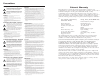
Precautions Safety Instructions • English This symbol is intended to alert the user of important operating and maintenance (servicing) instructions in the literature provided with the equipment. This symbol is intended to alert the user of the presence of uninsulated dangerous voltage within the product's enclosure that may present a risk of electric shock. Caution Read Instructions • Read and understand all safety and operating instructions before using the equipment.
FCC Class A Notice This equipment has been tested and found to comply with the limits for a Class A digital device, pursuant to part 15 of the FCC Rules. These limits are designed to provide reasonable protection against harmful interference when the equipment is operated in a commercial environment. This equipment generates, uses and can radiate radio frequency energy and, if not installed and used in accordance with the instruction manual, may cause harmful interference to radio communications.
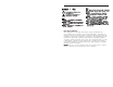
Table of Contents Chapter 1 • Introduction ......................................................... 1-1 About the P/2 DA2 WM F/EC F, AAP and D Models .................................................................................... 1-2 Features ...................................................................................... 1-2 Chapter 2 • Controls and Installation ........................... 2-1 Front and Rear Panels ................................................. 2-2 Front faceplate .....
Table of Contents, cont’d Templates ............................................................................... A-15 P/2 DA2 WM F mounting template ................................... A-15 P/2 DA2 WM F AAP mounting template ........................... A-16 P/2 DA2 D mounting template ..........................................
Introduction About the P/2 DA2 WM F/EC F, AAP, and D Models The P/2 DA2 WM F/F EC, AAP, and D models are one input, two output, high resolution VGA/XGA distribution amplifiers with audio. With a video bandwidth of 300 MHz, these distribution amplifiers are compatible with VGA, SVGA, VESA, XGA, and SXGA graphics cards, monitors, projectors, and LCD panels. The D model features Decora® faceplates and trim. For audio, the P/2 DA2 WM F/EC F and D feature a 3.5 mm female jack for input and a 3.
Controls and Installation Front and Rear Panels Unity – output signal level is same as that of input with no added peaking Front faceplate 50% – increases the output signal level and adds 50% of the maximum peaking to the signal N If the edges of the image seem to exceed their boundaries, or if thin lines and sharp edges look thick and fuzzy, try changing the level/peak setting.
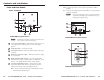
Controls and Installation, cont’d P/2 DA2 WM F/EC F rear panel 1 P/2 DA2 D rear panel 2 L AUDIO OUTPUT R 2 MED HIGH N15779 4 33-1663-01 A 05 08 Extron Electronics Anaheim, CA R POWER 12 V 0.
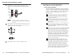
Controls and Installation, cont’d 3 Gain switch — To compensate for cable resistance and capacitance, use a small screwdriver to slide this switch to select the level of video gain that yields the sharpest, smear-free picture. Normal – Unity gain AUDIO OUTPUT R N15779 POWER 12 V 0.2 A MAX 33-1663-01 A 05 08 Extron Electronics Anaheim, CA HIGH VIDEO GAIN MED VIDEO OUTPUT NORM P/2 DA2 D L 3 High – Max.
Controls and Installation, cont’d 6 Power up all of the input and output devices. 7 The image should now display on screen. If it does not, double check steps 3 through 6 and make adjustments as needed. Refer to the section “Setting the DIP switches” in this chapter. 8 For the P/2 DA2 WM F, attach the P/2 DA2 WM F to the wall mounting bracket (see “Installing the mud ring bracket”). NOTE Do not disassemble the dogleg from the dogleg screw.
Controls and Installation, cont’d Cabling Connecting audio output The P/2 DA2 WM F cabling diagram below shows how to connect input and output devices to the distribution amplifier’s front panel. The P/2 DA2 WM EC F model has identical connectors. Before connecting audio output, determine whether your audio system is unbalanced or balanced. Then, follow the instructions below to connect unbalanced audio, or the instructions for “Balanced audio” to connect balanced audio.
Controls and Installation, cont’d Balanced audio To attach the distribution amplifier to a balanced audio system, do the following: 1. Adapter Plate Attach the audio cable to a balanced speaker input connector (tip, ring, and sleeve).
Controls and Installation, cont’d The center pole of the power input connector contains no conductor. Connect the conductors to the two outer poles only, exactly as shown here. C P/2 2 DA WM FE WER PO A D S R O ED ER NIT FF MO BU CAL LO DIO AU N/ G GAI AKIN PE1 50 P TM PINS ID 4 11 TO AU H N Once the input and output cables have been connected and tested on the P/2 DA2 WM F EC, the distribution amplifier can be easily installed in the Euro Channel.
Controls and Installation, cont’d Setting the internal jumpers Installing the P/2 DA2 D The jumpers (J2 and J6) inside the distribution amplifier are set at the factory for output to a local monitor. However, you can direct output to a data display by resetting the jumpers. Follow these steps and the illustration below to change the jumper settings.
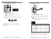
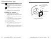
Controls and Installation, cont’d Wall Stud Installation Cable Wall Stud 3. Mount the distribution amplifier to the wall box with machine screws, as shown in the following illustration. Installation Cable Cable Clamp Cable Clamp Screws or Nails Screws or Nails Wall Box Extron P2 DA2 D IO IN D AU Wall opening is flush with edge of box. IN ER UT MP CO T OU OR NIT MO Attaching the wall box to a wall stud If attaching the wall box to wood, use four #8 or #10 screws or 10-penny nails.
Controls and Installation, cont’d Replacing the faceplate The front faceplate is replaced by removing the two rear panel mounting screws, replacing the faceplate, then reattaching the two screws, as shown below. L AUDIO OUTPUT R VIDEO OUTPUT N15779 POWER 12 V 0.
Specifications, Dimensions, and Parts Specifications Video Gain P/2 DA2 D ........................ Main output: 0 dB, 0.6 dB, 1.2 dB, selectable Local monitor output: unity P/2 DA2 WM F, P/2 DA2 WM F AAP Switchable: 0 dB, +1.2 dB, +2.2 dB(0.7 V, 0.8 V, or 0.9 V when input is 0.7 V and the gain/peaking switch is set to Unity, 50%, or 100%, respectively) Bandwidth P/2 DA2 D ........................
Specifications, Dimensions, Parts, cont’d Output impedance P/2 DA2 D ........................ 75 ohms P/2 DA2 WM F, P/2 DA2 WM F AAP 40 ohms, typical Max. propagation delay P/2 DA2 D ........................ 60 ns P/2 DA2 WM F, P/2 DA2 WM F AAP 18.8 ns Max. rise/fall time ....................... 4 ns Polarity .......................................... Positive or negative (follows input) Audio Gain ................................................
Specifications, Dimensions, and Parts, cont’d P/2 DA2 WM F Faceplate ................... 4.5” H x 4.6” W x 0.1” D (11.4 cm H x 11.7 cm W x 0.3 cm D) (2 gang) Box ............................. 2.6” H x 3.7” W x 1.6” D (6.6 cm H x 9.4 cm W x 4.1 cm D) P/2 DA2 WM F AAP Faceplate ................... 4.5” H x 8.3” W x 0.1” D (11.4 cm H x 21.1 cm W x 0.3 cm D) (4 gang) Box ............................. 2.6” H x 3.7” W x 1.6” D (6.6 cm H x 9.4 cm W x 4.1 cm D) Product weight P/2 DA2 D ........................ 0.
Specifications, Dimensions, and Parts, cont’d 1.700 [43.00] P/2 DA2 D faceplate dimensions .000 [0.000] P/2 DA2 WM F AAP faceplate dimensions .060 [1.524] .600 [15.500] .100 [2.540] 2.830 [71.882] 0.000 [0.000] 2.720 [69.088] 0.110 [2.794] 2.720 [70.000] 0.000 [0.000] Front View 0.000 [0.000] 0.060 [1.524] 0.100 [2.540] 0.225 [5.715] 1.600 [40.640] 1.445 [36.703] 1.550 [39.370] 0.155 [3.937] .0000 [0.000] 2X 0.050 [1.
Specifications, Dimensions, and Parts, cont’d Optional architectural adapter plates Parts and Accessories Included Parts The table below lists part numbers of the various models.
A-12 P/2 DA2 WM/EC/D/AAP Series • Appendix 1 1 1 1 1 1 2 3 RCA to BNC barrel (female to female) 2 S-video to S-video barrel (female to female) 2 F connector barrel (2) ¼" s tereo phono female (2) ¼" mono phono female (2) 3.5 mm mini stereo female 2 RJ-11 (female to female) 2 2 1 1 1 (1) 4-pin XLR female (1) 6-pin XLR female (2) 6-pin mini DIN (keyboard/mouse) (1) 3.5 mm, 5 pole captive screw terminal 1 contact closure switch/ LED show-me and 3.
A-14 Plate size 1 2 1 1 1 1 Adapter plate description 1 S-video female and 1 BNC female 1 S-video female and 3 RCA female 1 S-video female and 2 RCA female 1 BNC female and 2 RCA female 1 BNC female and (1) 3.5 mm mini stereo jack 1 RCA female and (1) 3.5 mm mini stereo jack RCA female and 3.5 mm mini stereo jack BNC female and 3.
Specifications, Dimensions, and Parts, cont’d P/2 DA2 WM F AAP mounting template P/2 DA2 D mounting template Cut-Out Template for Extron's P/2 DA2 WM F AAP Cut-Out Template for Extron's 4.50" (11.43 cm) P/2 DA2 D 2.79" (7.09 cm) Wall Plate 2.68" (6.80 cm) Wall Plate SURFACE CUT-OUT AREA FOR FURNITURE MOUNT 1.88" (4.78 cm) To install P/2 DA2 directly into furniture or wall, cut along this line. 4.50" (11.43 cm) 2.80" (7.11 cm) SURFACE CUT-OUT AREA FOR FURNITURE MOUNT 8.23" (20.90 cm) 7.
Specifications, Dimensions, and Parts, cont’d A-18 P/2 DA2 WM/EC/D/AAP Series • Appendix