
Manual


P/2 DA2 WM/EC/D/AAP Series • Controls and Installation
P/2 DA2 WM/EC/D/AAP Series • Controls and Installation
Controls and Installation, cont’d
2-15
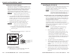
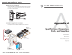
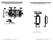
P/2 DA2 WM EC F Euro Channel installation
Once the input and output cables have been connected and
tested on the P/2 DA2 WM F EC, the distribution amplifier can
be easily installed in the Euro Channel.
Euro Channel installation
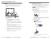
Setting the DIP switches
Two sliding-type DIP switches can be found on the faceplate of
the P/2 DA2 WM F/EC F.
To set the sliding-type DIP switches, slide the switch to
the on/closed or off/open position.
The two DIP switches provide proper ID bit termination for a
laptop computer that is not attached to a local monitor.
ID Pin 4 & ID Pin 11
ON — Set both pins to On if you are using the P/2 DA2
WM F/EC F with a laptop computer that is not
attached to a local monitor.
OFF — Set both pins to Off if you are attaching a local
monitor to the
P/2 DA2 WM F/EC F.
ID PIN 4
ID PIN 11
INPUT
AUTO POW
ER
ID PINS
U
N
IT
Y
GAIN/
PEAKING
1
00
%
5
0
%
11
4
AUDIO
BUFFERED
LOCAL MONITOR
WITH ADSP
T
M
INPUT
AUTO POW
ER
ID PINS
U
N
IT
Y
GAIN/
PEAKING
10
0
%
50
%
11
4
AUDIO
BUFFERED
LOCAL MONITOR
WITH ADSP
T
M
P/2 DA2 WM F EC
Euro Channel
P/2 DA2 W
M F EC
12
P/2 DA2 WM F
INPUT
AUTO POWER
ID PIN 4
UNITY
GAIN/PEAKING
100%
50%
ID PIN 11
AUDIO
BUFFERED
LOCAL MONITOR
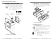
VGA Connector
Power (3.5 mm
Captive Screw
Connector)
Do not remove unless faceplate
is removed from wall.
Rear Cover Screws
Audio (3.5 mm
Captive Screw
Connector)
Positive
Negative
N/C
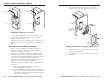
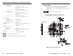
P/2 DA2 WM F wall mount installation
Once the input and output cables have been connected and the
P/2 DA2 WM F has been successfully tested, the faceplate may
be attached to the mounting bracket using the four supplied
screws.
N The center pole of the power input connector contains no
conductor. Connect the conductors to the two outer
poles only, exactly as shown here.
Wall mounting the P/2 DA2 WM F
2-14