User Guide PowerCage Fiber Optic Extenders PowerCage™ FOX Tx/Rx AV Fiber Optic Transmitter and Receiver 68-1914-01 Rev.
Safety Instructions • English Warning This symbol is intended to alert the user of important operating and maintenance (servicing) instructions in the literature provided with the equipment. Power sources • This equipment should be operated only from the power source indicated on the product. This equipment is intended to be used with a main power system with a grounded (neutral) conductor. The third (grounding) pin is a safety feature, do not attempt to bypass or disable it.
FCC Class A Notice This equipment has been tested and found to comply with the limits for a Class A digital device, pursuant to part 15 of the FCC Rules. Operation is subject to the following two conditions: 1. This device may not cause harmful interference. 2. This device must accept any interference received, including interference that may cause undesired operation.
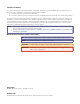
Contents Introduction.......................................................1 About this Guide................................................. 1 About the PowerCage FOX Tx/Rx AV Transmitter and Receiver....................................................... 1 System Compatibility....................................... 2 Cable Transmission Modes............................... 2 General System Operation............................... 2 Features...............................................................
PowerCage FOX Tx/Rx AV • Contents vi
Introduction This section gives an overview of the Extron PowerCage FOX Tx/Rx AV fiber optic extender boards, describes their significant features, and provides a sample application diagram. zz About this Guide zz About the PowerCage FOX Transmitter and Receiver zz Features WARNINGS: The PowerCage FOX Tx/Rx AV outputs continuous invisible light (Class 1 rated), which may be harmful and dangerous to the eyes; use with caution.
System Compatibility The PowerCage FOX Tx/Rx AV video units are compatible with the FOX Tx/Rx AV fiber optic video transmitter and receiver and with the FOX Series distribution amplifiers, switchers, and matrix switchers.
Features Digitized signal transmission — Digitized transmission ensures perfect signal transmission. The non-linearity of the fiber components does not affect signal quality. Light can be distributed and repeated without signal degradation or compression. Long distance transmission — Signals may be transmitted up to 2 km (6561 feet) over multimode (MM) fiber or up to 30 km (18.75 miles) over singlemode (SM) fiber.
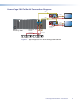
PowerCage FOX Tx/Rx AV Connection Diagram Fiber FOX 300 Rx RS-232 RS-232 OVER FIBER REMOTE POWER 12V 0.8A MAX O U T P U T S Y/VID B-Y/C Tx Rx R-Y OPTICAL Tx Rx Tx Rx AUDIO L R ALARM S-VID 1 2 Fiber Rx Tx 1 2 Tx Rx Tx Rx 12V 0.
Installation and Operation This section describes the installation and operation of the PowerCage FOX Tx/Rx AV Tx/ Rx, including: zz Installing the PowerCage FOX Tx/Rx AV zz Rear Panel Connections and Indicators zz PowerCage Front Panel Port, Control, and Indicators zz Operation CAUTION: Installation and service must be performed by authorized personnel only.
Video Connections a Video connectors — Three BNC connectors and one 4-pin mini DIN S-video connector are available for video input and output. The PowerCage FOX Tx/Rx AV inputs and outputs a single low resolution video signal (composite, S-video and low resolution component video). It is not compatible with RGB or HDTV 480p, 720p, or 1080i component video signals. The transmitter converts incoming signals to a proprietary format and passes them along the fiber optic cable to the PowerCage FOX Rx AV.
Audio Connections b Audio connector — Audio is input to the PowerCage FOX AV transmitter and output from the PowerCage FOX AV receiver through this 3.5 mm, 5-pole, captive screw connector. Input and output can be either two discrete mono or one stereo and can be balanced or unbalanced, depending on the wiring connections. The illustrations below show how to wire the audio sources and outputs. Do not tin the wires! R Tip Sleeve Balanced Audio Figure 3.
RS-232 Connections c RS-232 Remote port — The first three poles of the RS-232 Remote 5-pole captive screw connector are used for RS-232 configuration and control. Wire the connector as shown below. RS-232 OVER FIBER Tx Rx Pin Tx Rx Gnd Tx Rx Function Transmit data Receive data Signal ground Controlling Device Do not tin the wires! Receive (Rx) Transmit (Tx) Ground ( ) Bidirectional Figure 5.
SIS commands for the PowerCage FOX Tx/Rx AV are shown in the “Remote Communication and Control” section. NOTE: Both RS-232 Remote and RS-232 Over Fiber signals require fiber optic Link 1 and Link 2 for full functionality. If only Link 1 is enabled, the ability to configure the system through SIS commands is limited by the lack of return communication from the receiver to the transmitter.
Alarm e Alarm connector — When an alarm is connected to it, a warning signal is issued through the two rightmost poles of the 5-pole RS-232 Remote/Alarm captive screw connector when light signals have been disconnected, lost, or broken. REMOTE RS-232 ALARM 1 2 The alarm pins, labeled 1 and 2, (see the illustration at right) of this contact closure port act are shorted together when the signal is lost.
Daisy chain connection PowerCage FOX Rx AV receivers have a loop-out mode that allows a signal to be passed from the receiver along a daisy chain of to up to ten receivers, with a display device attached to each receiver. The loop-out mode is set using RS-232 commands (see the Daisy Chain command in the “SIS Control” section) or the FOX Extenders control program (refer to the program help file) for more information.
PowerCage 1600 Front Panel Port, Control, and Indicators The following features are on the front panel of the PowerCage 1600 enclosure. 1 2 3 4 5 6 7 8 9 10 11 COMM POWER ALARM 12 13 14 15 16 PSU 1 PSU 2 FAN 1 FAN 2 COMM SELECT CONFIG TEMP PowerCage 1600 1 Board Status LEDs for Multi-function Boards (up to 16 optional boards) 2 Power Supply Status LEDs 3 4 5 Fan Communi- ConfigStatus cation uration LEDs Selection Port Button (RS-232) 6 System Temperature Status LED Figure 9.
d e Comm Select button — Repeatedly press this button as necessary to select the board to be connected to the Configuration port (item e). The Comm LED (item a) for the selected board lights. Config port — This 2.5 mm mini stereo jack serves the same serial communications function as the Remote RS-232 port on the transmitter or receiver board, but is easier to access than the ports on the boards after the units have been installed and cabled. The 9-pin D to 2.
Operation After the transmitter, all receivers, and their connected devices are powered up, the system is fully operational. If any problems occur, verify that the cables are routed and connected properly and that all display devices have identical resolutions and refresh rates. If problems persist, call the Extron S3 Sales & Technical Support Hotline. See the contact numbers on the last page of this guide for the Extron office nearest you.
Remote Communication and Control This section describes the remote control operation of the PowerCage FOX Tx/Rx AV, including: zz SIS Control zz FOX Extenders Control Program RS-232 Ports The transmitter and receiver boards each have an RS-232 serial port on a 3-pin captive screw connector that can be connected to a host device such as a computer running the HyperTerminal utility, an RS-232 capable PDA, or a control system. The PowerCage enclosure has a Configuration port, a 2.
Remote Port on the PowerCage FOX Tx/Rx AV Board The Remote RS-232 captive screw port is located on the rear panel of the PowerCage FOX Tx/Rx AV. The pin assignments for this port are shown below. Pin Tx Rx Gnd REMOTE RS-232 ALARM Tx Rx 1 2 Function Transmit data Receive data Signal ground Do not tin the wires! Ground ( ) Receive (Rx) Transmit (Tx) NOTE: Bidirectional Controlling Device Ground ( ) Receive (Rx) Transmit (Tx) Cross the Tx and Rx lines once between the source and the target.
Symbols Used in this Guide When you are programming SIS commands, certain characters are most conveniently represented by the hexadecimal equivalent of their ASCII value. The table below shows the hexadecimal equivalent of each ASCII command: ASCII to Hex Conversion Table Space • NOTE: Apart from G (gain) and g (attenuation), upper- and lowercase characters can be used interchangeably in SIS commands for this product. For example, either “C” or “c” can be used to set the color value in the Color commands.
X1* X1( X2! X2@ X2# = Audio gain response (0 to 18) = Audio attenuation response (0 to -18) = SM (singlemode) or MM (multimode) = Tx (transmitter) or Rx (receiver) = Internal temperature in degrees Fahrenheit and Celsius: (xxxF xxC) Error Messages E10 — Invalid command E13 — Invalid parameter E14 — Not valid for this configuration PowerCage FOX Tx/Rx AV • Remote Communication and Control 18
Command/Response Table for SIS Commands ASCII Command (Host to Unit) Response (Unit to Host) Input video type X!\ TypX!] Set format X! for the selected input video signal type. For X!: 0 = Auto (default) 4 = Component 5 = S-video 6 = Composite View current input setting \ X!] Display the current input video format. Color value X*C ColX*] Select color value X*. X* = 0 through 127. Default = 64. Increment color value +C ColX*] Select the next higher color value (increase color value by 1).
Command ASCII Command (Host to Unit) Response (Unit to Host) Additional Description Picture adjustments, continued Video mute: Enable mute 1B Blk1] Mute the selected input. Disable mute 0B Blk0] Disable mute on the selected input. View current blanking status B X%] Display current blanking status X%. For X%: 0 = Disable blanking or mute. 1 = Enable blanking or mute. Specify output format 6*X1%# SynX1%] Set format X1% of the output video signal.
Command ASCII Command (Host to Unit) Response (Unit to Host) Additional Description Audio gain and attenuation, continued Increment audio level +G +g AudX1#] AudX1#] Increase the gain (G) or attenuation (g) of audio level X1# by 1 dB. X1# = –18 through +10 dB. Default = 0. Decrement audio level -G -g Aud X1#] Aud X1#] Decrease the gain (G) or attenuation (g) by 1 dB. Audio level X1# = –18 through +10 dB.
Command ASCII Command (Host to Unit) Response (Unit to Host) Additional Description Disable and enable return link (link 2) Disable return link back to transmitter 66*0*0# Rle*0*0] Disable the return link from the receiver to the transmitter. Enable return link (normal mode) 66*0*1# Rle*0*1] Enable the return link to the transmitter (default). Daisy chain 66*0*2# Rle*0*2] Enable daisy chain mode on the receiver.
ASCII Command (Host to Unit) Response (Unit to Host) View Link 1 Status 1S X%] Displays Link 1 status X%. For X%: 0 = no link 1 = link present View Link 2 Status 2S X%] Display Link 2 (return link) status X%. View input video status 3S X%] Display input video status X%. For X%: 1 = a video signal is present. 0 = no video signal is present. View input audio status 4S X%] Display input audio status X%. For X%: 1 = an audio signal is present. 0 = no audio signal is present.
SIS Command Validity Table If only one fiber optic channel is enabled, the ability to configure the system through SIS commands is limited by the lack of return communication from the receiver to the transmitter. zz All commands issued through the transmitter are valid because the transmitter-toreceiver link (link 1) allows signals to be forwarded to the receiver. However, responses to queries originating from the transmitter about the status of the receiver return invalid data.
Figure 12. Software Button on the Disk Opening Screen 3. On the Control Software screen, scroll to locate the FOX Extenders line, and click the Install link in the far right column. Figure 13. Install Link for the FOX Extenders Software 4. Follow the on-screen instructions to complete the installation. By default, the installer program creates a folder for the software at C:\Program Files\Extron\FOX_Extenders (all Windows systems except Windows 7) or C:\Program Files (x86)\Extron\FOX_Extenders (Windows7).
Starting the Control Program Start the Extron FOX Extenders Control Program as follows: 1. Set up and power on the units as described in the Installation and Operation section. Connect the computer to one of the control ports on either the transmitter or receiver. 2. Click Start > All Programs > Extron Electronics > FOX Extender WCP > FOX Extender WCP or click on the desktop icon (shown at right). The Communication Setup window opens. Figure 15. Communication Setup window 3.
FOX Extenders Main Window Figure 16. FOX Extenders Main Window The FOX Extenders Control Program main window contains the following: Menu bar and toolbar The File, Tools, and Help menus on the menu bar provide access to various functions, including connecting to and disconnecting from the FOX Tx/Rx AV; viewing information about your unit such as firmware version, part number, and model name; uploading firmware; refreshing the status display; and opening the FOX Extenders control program help file.
Status area The Status area provides visual indications of the connection status: Figure 18. Status Area zz Video indicator — Shown in green when a composite, S-video, or component video signal is present zz Audio indicator — Shown in green when the transmitter detects an audio signal at or more than 35 dB below the nominal level. Stays green until the signal falls below this threshold continuously for 10 seconds.
Mute area Select a radio button in the Mute area to mute or unmute the video or audio signal. Video Adjustment area Use the sliders to adjust the Color, Tint, Contrast, and Brightness of the picture that is displayed. All four of these variables can be adjusted to between 0 and 127, with the current value displayed in the text box to the right of the corresponding slider.
Audio Adjustment area zz Audio Gain/Attenuation — A slider control enables you to adjust the input audio gain or attenuation value from –18 dB to +10 dB in 1.0 dB increments. NOTE: zz Changes to the input gain or attenuation are made in the transmitter. If your computer is connected to the receiver and Link 2 is not active, the gain and attenuation values are grayed out and cannot be changed.
Figure 21. Personal Information Form 4. Follow the instructions on the rest of the download screens to download the firmware update from the Extron website, and start the Extron Installation Program to extract the firmware file and place it in a folder identified in the program window. NOTE: Take note of the folder to which the firmware file is saved. Folder where firmware is installed Figure 22.
4. Follow the instructions on the download screens to save the installer file to your computer. 5. In Windows Explorer or another file browser, locate the Firmware Loader executable file in your computer’s file system and double-click on it to open it. 6. Follow the instructions on the Installation Wizard screens to install the Firmware Loader on your computer. Unless you specify otherwise, the installer program places the Firmware Loader file, “FWLoader.exe” at C:\Program Files\Extron\FWLoader.
3. Click Connect. The Firmware Loader window appears. Figure 25. Extron Firmware Loader Window 4. In the Devices field, select your PowerCage FOX Tx/Rx AV unit, then select New Firmware for Selected Devices from the File menu. Figure 26.
5. The Choose Firmware File window opens. Figure 27. Choose Firmware File Window 6. Navigate to and select the new firmware file, which has a .bin extension, and click Open. The Choose Firmware File window closes. CAUTION: NOTE: The firmware file must have a .bin extension. Uploading other file types can cause the switcher to stop functioning.
Reference Information This section discusses the specifications, part numbers, and installation instructions for the PowerCage FOX Tx/Rx AV Tx/Rx Fiber Optic Extenders. Topics that are covered include: zz Specifications zz Part Numbers zz Installing the FOX Tx/Rx AV Board in the PowerCage 1600 Enclosure Specifications NOTES: The PowerCage FOX Tx/Rx AV boards are available in singlemode or multimode versions. The optional PowerCage FOX boards are class 1 laser products.
Video NOTE: For PowerCage FOX Tx/Rx AV boards, the analog video input signal is digitized pixel for pixel in the transmitter, sent digitally through the fiber cable, and converted back to analog video in the receiver. Gain ����������������������������������������������� Standards Input ��������������������������������������� Output ������������������������������������ Decoder type ���������������������������������� Unity NTSC 3.58, NTSC 4.43, PAL, SECAM, autodetected NTSC 3.
Nominal levels �������������������������������� +4 dBu (1.23 Vrms), -10 dBV (316 mVrms) Maximum level ������������������������������� +17 dBV, (unbalanced) at 1% THD+N NOTE: 0 dBu = 0.775 Vrms, 0 dBV = 1 Vrms, 0 dBV ≈ 2 dBu Audio output Number/signal type ������������������������ 1 stereo, balanced/unbalanced or 2 mono, balanced/unbalanced Connector �������������������������������������� (1) 3.
Product weight PowerCage enclosure �������������� PowerCage FOX boards ����������� Shipping weight PowerCage enclosure �������������� PowerCage boards ������������������� Vibration ���������������������������������������� Regulatory compliance Safety �������������������������������������� EMI/EMC ��������������������������������� MTBF ��������������������������������������������� Warranty ���������������������������������������� 11.6 lbs (5.3 kg) 1.1 lbs (0.
Part Numbers PowerCage FOX Tx/Rx AV PowerCage Enclosure and Boards Part Number PowerCage 1600 Enclosure 60-978-01 PowerCage FOX Tx AV MM (transmitter) 70-702-11 PowerCage FOX Tx AV SM (transmitter) 70-702-12 PowerCage FOX Rx AV MM (receiver) 70-702-21 PowerCage FOX Rx AV SM (receiver) 70-702-22 Included Parts Included Parts Part Number MM or SM fiber patch cable 5-pole 3.5 mm blue captive screw 2-pole 3.
Installing the FOX Tx/Rx AV Board in the PowerCage 1600 Enclosure Up to 16 single slot or 8 dual slot boards can be inserted into the PowerCage enclosure. The boards may vary with each installation depending on the configuration and use. NOTES: All boards are “hot-swappable,” meaning that they can be installed or removed without turning off or disconnecting the power to the PowerCage Enclosure. Use ESD precautions when installing the FOX 3G HD-SDI board to avoid damaging it.
16 Available Single Board Slots (8 double board slots) Tx Tx REMOTE RS-232 ALARM Tx Rx RGB OUTPUT SHARP GAIN 1 2 Y/VID HD/SDI OUTPUTS Tx Rx Tx REMOTE RS-232 ALARM 1 2 Rx e ag rC we AV Po X Rx FO VIDEO 1 2 3 4 Tx Rx MODE HD/SDI INPUT MONO AUDIO OUTPUT Tx Rx Align board and slide into slot. RS-232 OVER FIBER Hz /60 50 V X. 40 MA 5A 0-2 10 ED LI ST 23 1T . .E I.
Extron® Warranty Extron Electronics warrants this product against defects in materials and workmanship for a period of three years from the date of purchase.