
User Guide Owner manual

1 2
REMOTE
RS-232
RS-232
OVER FIBER
Tx Rx
Tx
ALARM
Rx
OUTPUT
RGB
PowerCage
FOX RX RGB
Tx Rx
L R
AUDIO
MONO
AUDIO OUTPUT
1 2
SHARP
GAIN
Y/VID
C
INPUT
PowerCage
MTP R AV
Tx Rx
HD/SDI INPUT HD/SDI OUTPUTS
MODE
PowerCage
FOX 3G HD-SDI
1 2
REMOTE
RS-232
RS-232
OVER FIBER
Tx Rx
Tx
ALARM
Rx
OUTPUT
RGB
PowerCage
FOX RX RGB
Tx Rx
L R
AUDIO
5A MAX.
100-240V 50/60Hz
N157 78
C
US
LIST ED
1T23
I.T.E.
1 2
REMOTE
RS-232
RS-232
OVER FIBER
Tx Rx
Tx
ALARM
Rx
VIDEO
1
2
3
4
PowerCage
FOX Rx AV
Tx Rx
L R
AUDIO
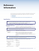
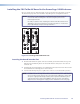
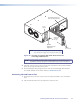
Align board
and slide
into slot.
Screws
(2 per board)
16 Available Single Board
Slots (8 double board slots)
Power
Supply
Optional
Redundant Power
Supply Slot
NOTE: Power supplies can occupy only these two power supply
slots. (Each power supply can be mounted in either slot.)
Figure 30. Inserting a PowerCage FOX Tx/Rx AV Board into the
PowerCage 1600 Enclosure
NOTE: Use a screwdriver or other tool to fully tighten the screws after initial
installation and any subsequent removal and replacement of the board.
4. If desired, connect power to the enclosure and verify that the fans, board, and LEDs
power up correctly; then disconnect power.
5. Finish installing the PowerCage Enclosure. Refer to the PowerCage 1600 Enclosure
User Guide, available on the Extron website at www.extron.com.
Removing a Board from a Slot
1. Completely loosen the two screws on the rear panel board that secure the board in
place.
2. Slide the board out from the rear and remove it from the slot.
PowerCage FOX Tx/Rx AV • Reference Information 41