User Guide Fiber Optic Extenders PowerCage FOX Tx/Rx VGA PowerCage FOX Tx/Rx DVI PowerCage FOX Tx/Rx DVI Plus High Resolution Fiber Optic Transmitters and Receivers 68-1911-01 Rev.
Safety Instructions • English Warning This symbol is intended to alert the user of important operating and maintenance (servicing) instructions in the literature provided with the equipment. Power sources • This equipment should be operated only from the power source indicated on the product. This equipment is intended to be used with a main power system with a grounded (neutral) conductor. The third (grounding) pin is a safety feature, do not attempt to bypass or disable it.
FCC Class A Notice This equipment has been tested and found to comply with the limits for a Class A digital device, pursuant to part 15 of the FCC Rules. Operation is subject to the following two conditions: 1. This device may not cause harmful interference. 2. This device must accept any interference received, including interference that may cause undesired operation.
Contents Introduction............................................. 1 Remote Control....................................... 16 About this Manual............................................ 1 About the PowerCage FOX Transmitters and Receivers......................................................... 2 General System Operation............................ 3 System Compatibility.................................... 4 Cable Transmission Modes............................ 5 Features.................................
Introduction WARNING: The PowerCage™ FOX Tx/Rx units output continuous invisible light, which may be harmful to the eyes; use with caution. • Do not look into the rear panel fiber optic cable connectors or into the fiber optic cables themselves. • Plug the attached dust caps into the optical transceivers when the fiber optic cable is unplugged.
This guide includes instructions for an experienced installer to install, configure, and operate the equipment. NOTES: • In this manual, the term “PowerCage FOX” refers to either an analog RGB video or a DVI video unit. Where differences exist between the VGA and DVI models, the full name of the unit is used. • In this manual, the term “PowerCage FOX DVI” refers to either the Plus or non-Plus model, unless a model is specifically named.
General System Operation The PowerCage FOX VGA transmitter inputs VGA-UXGA RGB video. The PowerCage FOX DVI Plus transmitter inputs a single link of DVI video. Both transmitters input audio and one-way (transmitter-to-receiver) RS-232 serial communication (for applications such as projector control). The transmitters convert all of the inputs to them into a proprietary signal and output the signal on a single fiber optic cable to the receiver.
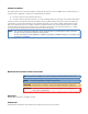
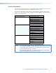
System Compatibility The fiber optic signal output from a PowerCage FOX Tx DVI Plus transmitter can be received only by a PowerCage FOX Rx DVI Plus or FOXBOX Rx DVI Plus receiver. The fiber optic signals from all other units are interchangeably compatible between VGA and DVI units, Plus and non-Plus units, and PowerCage FOX, FOXBOX, and FOX 500 units as shown in the following table.
Cable Transmission Modes The transmitters and receivers are further categorized by the type of fiber optic cable, multimode or singlemode, which define the effective range of transmission: • • Multimode — Long distance, up to 2 km (6,560 feet) (depending on the fiber cable) • PowerCage FOX Tx VGA MM • PowerCage FOX Rx VGA MM • PowerCage FOX Tx DVI (Plus and non-Plus) MM • PowerCage FOX Rx DVI (Plus and non-Plus) MM Singlemode — Very long distance, up to 30 km (18.
Audio input gain/attenuation — The input audio level can be adjusted within a range of -18 dB (attenuation) to +10 dB (gain) via the RS-232 link. Audio output — The receivers output balanced or unbalanced stereo audio on a 3.5 mm, 5-pole captive screw terminal. Links monitoring — The front panels of the transmitters and receivers have indicators for monitoring both fiber optic links.
Installation and Operation This section describes the installation and operation of the PowerCage FOX VGA and PowerCage FOX DVI, including: • Mounting the Units • Connections and Indications • PowerCage Front Panel Port, Control, and Indicators • Operation Mounting the Units The PowerCage FOX transmitter or receiver must be installed in an Extron PowerCage enclosure (see “Installing a Board in the Enclosure” on page 42.
c Audio Input connector (transmitters) — Connect a balanced or unbalanced stereo or mono audio input to this connector. The connector is included with transmitter, but you must supply the audio cable (see figure 3 to wire a captive screw connector for the appropriate input type and impedance level.) Use the supplied tiewrap to strap the audio cable to the extended tail of the connector.
f g REMOTE RS-232 ALARM Alarm outputs port — For remote monitoring of the status of the Rx fiber optic link, connect a locally-constructed or furnished monitoring device to the unit to be monitored via two poles of this 5-pole captive screw connector on the unit to be monitored. When the unit does not detect light on its Rx connector, pin 1 and pin 2 of this port are shorted together.
h Receiver fiber optic connectors and LEDs — WARNING: These units output continuous invisible light, which may be harmful to the eyes; use with caution. For additional safety, plug the attached dust caps into the optical transceivers when the fiber optic cable is unplugged. NOTES: • You can connect the transmitter to one or more receivers in one of three ways: • One way (transmitter-Tx-to-receiver-Rx) only — Connect fiber cable é (from transmitter connector å) only.
i VGA Output connector (PowerCage FOX Rx VGA only) — Connect an analog VGA-UXGA RGB video display to this 15-pin HD female connector. NOTE: j DVI-I Output connector (PowerCage FOX DVI only) — Connect a DVI video display to this DVI-I connector (see “DVI connector (PowerCage FOX DVI)“ on page 12 for pin assignments.) NOTE: k You can set the receiver to output the desired video format: RGBHV or RGsB. RGBHV is the default (see the “Remote Control”section.
Making Connections DVI connector (PowerCage FOX DVI) Figure 8 defines the DVI pin assignments.
RS-232 connections The RS-232 Over Fiber port is for transmission of serial signals, such as projector control signals, between the transmitter and receiver. The Remote RS-232 port is for remote control of the transmitter and receiver.
PowerCage Front Panel Port, Control, and Indicators The following features are on the front panel of the PowerCage enclosure. 1 2 3 COMM POWER ALARM 14 15 16 PSU 1 PSU 2 FAN 1 FAN 2 COMM SELECT TEMP CONFIG PowerCage 1600 13 14 15 16 17 18 Figure 11. PowerCage Front Panel m Comm LED (16 board locations) — This LED lights to indicate that the board at this location is selected for connection to the Configuration port (item q).
q Configuration port — This 2.5 mm mini stereo jack serves the same serial communications function as the Remote RS-232 port on the transmitter or receiver board, but is easier to access than the ports on the boards after the units have been installed and cabled. The 9-pin D to 2.5 mm mini jack TRS RS‑232 cable, included with the PowerCage enclosure, but also available separately, part number 70-335-01 (see figure 12), can be used for this connection. 6 feet (1.
Remote Control This section describes the remote control operation of the PowerCage FOX DVI and PowerCage FOX VGA, including: • Serial Ports • Simple Instruction Set Control • FOX Extender Program Control Serial Ports The transmitter and receiver boards each have an RS-232 serial port on a 3-pin captive screw connector that can be connected to a host device such as a computer running the HyperTerminal utility, an RS-232 capable PDA, or a control system.
PowerCage Configuration Port The Extron 9-pin D to 2.5 mm mini jack TRS RS‑232 cable, included with the PowerCage enclosure, but available separately, part #70-335-01 (see figure 14) can be used for connection to the Configuration port. 6 feet (1.8 m) 1 6 9 5 Tip Ring 9-pin D Connection TRS Plug Pin 2 Pin 3 Pin 5 Computer Rx line Computer Tx line Computer signal ground Tip Ring Sleeve Sleeve (Gnd) Figure 14.
Simple Instruction Set Control Host-to-Unit Instructions SIS commands consist of one or more characters per field. No special characters are required to begin or end a command character sequence. When a command is valid, the unit executes the command and sends a response to the host device. All responses from the unit to the host end with a carriage return and a line feed (CR/LF = ]), which signals the end of the response character string. A string is one or more characters.
Unit-initiated Messages When a local event, such as an equipment power-up, occurs, the unit responds by sending a message to the host. The unit-initiated messages are listed below: (c) Copyright 2010, Extron Electronics PowerCage FOX Tx VGA, Vx.xx, 70-699-xx]] - or (c) Copyright 2010, Extron Electronics PowerCage FOX Rx VGA, Vx.xx, 70-699-xx]] - or (c) Copyright 2010, Extron Electronics PowerCage FOX Tx DVI, Vx.xx, 70-700-xx]] - or (c) Copyright 2010, Extron Electronics PowerCage FOX Rx DVI, Vx.
Error Responses When the unit receives a valid SIS command, it executes the command and sends a response to the host device. If the unit is unable to execute the command because the command is invalid or it contains invalid parameters, the unit returns an error response to the host.
Command/Response Table for SIS Commands Command ASCII Command Response (host to unit) (unit to host) 1B 0B B Blk1] Blk0] Additional description Video mute Mute output Unmute output Show video mute status X!] Blank the video output. Output video. Video mute status is X!.
Command/response table for SIS commands (continued) Command ASCII Command Response (host to unit) (unit to host) Additional description Pixel phase NOTE: When the controlling PC is connected to the receiver, the PowerCage FOX can perform this command only if the receiver-Tx-totransmitter-Rx fiber cable is connected. The unit returns the E14 error if the Rx fiber is not connected.
Command/response table for SIS commands (continued) Command ASCII Command Response (host to unit) (unit to host) 1Z 0Z Z Amt1] Amt0] 55*0# 55*1# 55# Img0] Img1] 55*2# Img] Additional description Audio mute Mute the audio Unmute the audio Show audio mute statue X!] Silence the audio output of the receiver. The receiver outputs audio. Audio mute status is X!.
Command/response table for SIS commands (continued) Command ASCII Command Response (host to unit) (unit to host) Additional description I 1LnkX1(•2LnkX1(•RGBX1(•AudX1(•X2!•X2@] The unit responds with the current status (signal detected) of optical link 1, optical link 2, the video input, and the audio link; the fiber optic transmission mode (singlemode or multimode); and the device type (Tx or Rx).
FOX Extender Program Control The Extron FOX Extender program, which communicates with the transmitter and receiver pair via the Remote RS-232 port of either unit or the PowerCage Configuration port, provides an easy way to operate the pair. The program is compatible with Windows 2000, Windows XP, or later. Updates to this program can be downloaded from the Extron website (www.extron.com). Installing the Software The program is contained on a DVD. To install the software, insert the DVD into the drive.
2. Select the Com port to which your transmitter or receiver is connected. Click OK. The FOX Extender program window appears (see figure 16). Figure 16. FOX Extender Program Window NOTE: Only one fiber optic cable, transmitter-Tx-to-receiver-Rx, is required for serial command transmission. However, if you connect only one fiber optic cable, there will be reduced control program functionality on the Rx unit.
Status area The Status area provides visual indications of the connection status. • RGB indicator — This indicator is green when the transmitter detects a sync signal on its video input: • Horizontal sync (H) (for RGBHV video) • Composite sync (S) (for RGBS video) • Green (Sync on green) (G) (for RGsB or RsGsBs video) • DVI video • Audio indicator — This indicator is green when the transmitter detects a low level audio signal for a short period.
Mute area Click the Video Mute radio button, the Audio Mute radio button, or both in the Mute area to turn the video and audio mutes on and off. NOTES: • When the video output is RGB and the output is muted, the receiver mutes the red, green, and blue planes, but leaves the sync planes (horizontal and vertical or composite sync) live so that there is no loss of sync in the display device. • When you mute or unmute the output, the setting is changed in the receiver.
Output Configuration area Sync Format radio buttons — The PowerCage FOX receiver outputs RGBHV or RGsB video depending on the input to the transmitter only. The radio buttons in this area have no effect on the PowerCage FOX receiver. Refer to the FOX 500 User Guide if you are using one of those products to receive the fiber optic signal, as the video output of those products can be configured.
Audio Adjustment area Audio Gain/Attenuation slider — Click and drag the Audio Gain/ Attenuation slider control to select the input audio gain or attenuation value, from -18 dB to +10 dB in 1.0 dB increments. NOTE: When you make input gain or attenuation changes, the setting is changed in the transmitter.
Firmware upgrade Firmware can be upgraded for each unit via the PowerCage Configuration port using the Extron Firmware Loader utility from the Windows-based control program. NOTES: • Firmware can be upgraded through the PowerCage Configuration port only. • When firmware upgrades are available, they are unique to the unit: • A unique transmitter firmware upgrade for the Tx unit • A unique receiver firmware upgrade for the Rx unit.
3. Complete the Personal Information form (see figure 21) and click the Download button. 3 Figure 21. Personal Information Form 4. Follow the instructions on the rest of the download screens to download the firmware update from the Extron website, start the Extron Installation Program to extract the firmware file, and place it in a folder identified in the program window. NOTE: Note the folder to which the firmware file is saved (see figure 22). Folder where firmware is installed Figure 22.
Loading the firmware to the unit To load a new version of firmware to your transmitter and receiver, open the Firmware Loader software from within the FOX Extender program. Your serial port on your computer must be connected to the PowerCage Configuration port only (see item q in the PowerCage Front Panel Port, Control, and Indicators section for more information.) 1. In the FOX Extender program, click the Firmware Loader button ( NOTE: ) on the tool bar.
3. From the drop-down menus on the RS-232 screen, select the appropriate Com port number and baud rate (the default is 9600). 4. Click OK. The Firmware Loader window appears (see figure 24). 5 Figure 24. Extron Firmware Loader Window 5. Select the PowerCage FOX unit and click File > Open. The Choose Firmware File screen appears (see figure 25). 6 6 Figure 25. Choose Firmware File Window 6. Navigate to and select the new firmware file. Click Open. The Choose Firmware File window closes.
7. In the Firmware Loader window, click Begin (see figure 26). The Total Progress and Progress Status bars show the progress of the upload. The firmware upload to the switcher may take several minutes. Once the status bars have progressed from 0% to 100%, and Status is listed as Completed, the firmware loader utility resets the unit. 7 Figure 26. Firmware Loader Screen 8. Click Exit to close the Firmware Loader.
Reference Information This section provides the specifications, part numbers, and installation instructions for the PowerCage FOX DVI and PowerCage FOX VGA. • Specifications • Part Numbers • Installing a Board in the Enclosure Specifications NOTE: The PowerCage FOX boards are available in singlemode or multimode versions. NOTE: The optional PowerCage FOX boards are class 1 laser products. They meet the safety regulations of IEC-60825, FDA 21 CFR 1040.10, and FDA 21 CFR 1040.11.
Optical loss budget Singlemode ����������������������������� 13 dB, maximum Multimode ������������������������������� 7 dB, maximum Maximum channel data rate ����������� 4.25 Gbps Video — PowerCage FOX Tx/Rx VGA NOTE: For PowerCage FOX VGA boards, the analog video input signal is digitized pixel for pixel in the transmitter, sent digitally through the fiber cable, and converted back to analog video in the receiver.
Video input — PowerCage FOX Tx DVI, PowerCage FOX Tx DVI Plus Number/signal type ������������������������ 1 single link DVI-D (or HDMI*) Connector �������������������������������������� 1 female DVI-I NOTE: *Appropriate DVI-D to HDMI cables or adapters are required for HDMI signal input/output. The PowerCage FOX DVI and DVI Plus boards can be used to distribute HDMI signals if you use a DVI-to-HDMI adapter. However, when using HDMI signals, these units do not transmit audio and CEC signals.
Control/remote Serial control ports Enclosure ��������������������������������� 1 bidirectional RS-232, 2.5 mm mini stereo jack (front panel) PowerCage FOX boards Control ������������������������������ 1 bidirectional RS-232, 3.5 mm captive screw connector, 5 pole (uses 3 poles; shared with the alarm port) Pass-through ���������������������� 1 RS-232, 3.
Part Numbers PowerCage FOX part numbers The PowerCage FOX units must be installed in a PowerCage 1600 enclosure.
Cables Accessory Part number VGA M-M MD, 3' to 100' (0.9 m to 30.4 m) (molded) 26-238-nn VGA M-M BK, 3' to 100' (0.9 m to 30.4 m) (backshell) 26-238-nn VGAP M-M MD, 3' to 25' (0.9 m to 7.6 m) (molded) (plenum) 26-439-nn VGAP M-M BK, 35' to 100' (10.6 m to 30.4 m) (backshell) (plenum) 26-439-nn VGA-A M-M MD (with audio), 3' to 50' (0.9 m to 15.2 m) (molded) 26-490-nn VGA-A M-M BK (with audio), 3' to 50' (0.9 m to 15.
Installing a Board in the Enclosure Up to 16 single slot or 8 dual slot input/output boards can be inserted into the PowerCage enclosure. The PowerCage transmitters and receivers are all dual slot boards. NOTE: The boards are hot-swappable, and can be installed or removed without disconnecting power to the PowerCage enclosure. Use ESD precautions when installing a board to avoid damaging the board. Keep the board in the anti-static bag until needed. Use proper grounding techniques during installation. 1.
Extron® Warranty Extron Electronics warrants this product against defects in materials and workmanship for a period of three years from the date of purchase.