User Guide Fiber Optic Extenders PowerCage FOX Tx/Rx HDMI High Resolution Fiber Optic Transmitters and Receivers 68-1994-01 Rev.
Safety Instructions • English Warning This symbol is intended to alert the user of important operating and maintenance (servicing) instructions in the literature provided with the equipment. Power sources • This equipment should be operated only from the power source indicated on the product. This equipment is intended to be used with a main power system with a grounded (neutral) conductor. The third (grounding) pin is a safety feature, do not attempt to bypass or disable it.
FCC Class A Notice This equipment has been tested and found to comply with the limits for a Class A digital device, pursuant to part 15 of the FCC Rules. Operation is subject to the following two conditions: This device may not cause harmful interference. 1. This device must accept any interference received, including interference that may cause undesired operation.
Conventions Used in this Guide Notifications the following are used: DANGER: A danger indicates a situation that will result in death or severe injury. WARNING: A warning indicates a situation that has the potential to result in death or severe injury. CAUTION: A caution indicates a situation that may result in minor injury. ATTENTION: Attention indicates a situation that may damage or destroy the product or associated equipment. NOTE: TIP: A note draws attention to important information.
Contents Introduction............................................. 1 Remote Control....................................... 17 About this Guide.............................................. 1 About the PowerCage FOX HDMI Transmitters and Receivers............................... 2 Transmitter.................................................... 2 Receiver........................................................ 2 Transmitter and Receiver............................... 3 System Compatibility...................
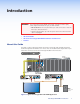
Introduction WARNING: The PowerCage™ Tx/Rx HDMI units output continuous invisible light, which may be harmful to the eyes; use with caution. • Do not look into the rear panel fiber optic cable connectors or into the fiber optic cables themselves. • Plug the attached dust caps into the optical transceivers when the fiber cable is unplugged.
This guide includes instructions for an experienced installer to install, configure, and operate the equipment. About the PowerCage FOX HDMI Transmitters and Receivers The PowerCage FOX HDMI Fiber Optic Extender is an ultra-high performance fiber optic transmitter and receiver set for long haul transmission of HDCP-compliant HDMI video, audio, and RS-232 control signals over fiber optic cabling. The transmitter and receiver can extend HDMI signals up to 30 km (18 miles).
With the appropriate adapter, the single link of HDMI video output by the receiver can be converted to DVI-D video. The receiver has built-in alternating pixels, color bars, and grayscale test patterns to assist in setting up the display equipment. Transmitter and receiver The transmitter and receiver have many controls, including image and audio adjustments, and available under RS-232 Simple Instruction Set (SIS™) control.
Features Ultra high performance — Offers pixel-for-pixel HDMI or DVI-D (with an adapter) video transmission, up to 1920 x 1200 at 60 Hz (in plus mode) or 1600 x 1200 at 60 Hz (in non-plus mode). Video input — The transmitter accepts a single link of HDMI or DVI-D video. EDID emulation mode (Display Data Channel [DDC]) — The PowerCage FOX Tx HDMI transmitter provides a selector switch for specifying the rate of the incoming digital video signal.
Installation and Operation This section describes the installation and operation of the PowerCage FOX HDMI, including: • Mounting the Units • Rear Panel Connections, Controls, and Indications • Transmitter Side Panel Controls • PowerCage Front Panel Port, Control, and Indicators • Operation Mounting the Units The PowerCage FOX transmitter or receiver must be installed in an Extron PowerCage enclosure (see “Installing a Board in the Enclosure” on page 42.
c RS-232 RS-232 Over Fiber port — If you want the transmitter and receiver OVER FIBER system to pass serial command signals between the transmitter and receiver, for example for serial control of a projector, connect the host device to the Tx Rx transmitter and the slave device to the receiver via the leftmost three poles on the left (Tx, Rx, and _) of the 5-pole captive screw connectors on both units (see “RS-232 connectors“ on page 11 to wire this connector).
f Transmitter fiber optic connectors and LEDs — WARNING: These units output continuous invisible light, which may be harmful to the eyes; use with caution. For additional safety, plug the attached dust caps into the optical transceivers when the fiber cable is unplugged. NOTES: • Ensure that you use the proper fiber cable for your transmitter and receiver pair. Typically, singlemode fiber has a yellow jacket and multimode cable has an orange or aqua jacket.
Receiver fiber optic connectors and LEDs — WARNING: These units output continuous invisible light, which may be harmful to the eyes; use with caution. For additional safety, plug the attached dust caps into the optical transceivers when the fiber cable is unplugged. NOTES: • You can connect the transmitter to one or more receivers in one of three ways: • One way (transmitter to receiver) only — Connect a fiber cable to connector å from transmitter connector ä only (see figure 3).
h HDMI output connector — Connect a video display to this HDMI connector. See “HDMI connectors“ on the next page for pin assignments and to use the LockIt HDMI Cable Lacing Bracket to secure the connector to the receiver. i Audio output connector (receivers) — This 5-pole, 3.5 mm captive screw connector outputs the transmitted, unamplified, line level audio. Connect audio devices, such as an audio amplifier or powered speakers.
Making Connections HDMI connectors Figure 6 defines the pinout for the HDMI protocol.
3. Place the LockIt lacing bracket on the screw and against the HDMI connector, then tighten the screw to secure the bracket (c). ATTENTION: Do not overtighten the HDMI connector mounting screw. The shield to which it fastens is very thin and can easily be stripped. 4. Loosely place the included tie wrap around the HDMI connector and the LockIt lacing bracket as shown (d). 5.
Alarm outputs connectors REMOTE RS-232 ALARM Tx Rx 1 2 Pin 1 and pin 2 are shorted together when no light is detected. Do not tin the wires! Figure 9. Alarm Connector NOTE: The length of exposed wires is critical (see the RS-232 connectors NOTE on the previous page). Audio output connector See figure 10 to properly wire a captive screw output connector. The connector is included with transmitter, but you must supply the audio cable.
Transmitter Side Panel Controls 2 The following features are on the PowerCage HDMI Tx transmitter, and are accessible though the cut on the left side of the module enclosure (see figure 11). 1 1 2 Figure 11. Transmitter Side Panel Controls a b DIP switches — • Switch 2 (Audio) — This switch selects which audio input, the audio embedded in the HDMI input or the analog audio, is sent to the receiver. On (left) selects the digital (embedded) audio and off (right) selects the analog audio.
PowerCage Front Panel Port, Control, and Indicators The following features are on the front panel of the PowerCage enclosure (see figure 12). 1 2 3 COMM POWER ALARM 14 15 16 PSU 1 PSU 2 FAN 1 FAN 2 COMM SELECT TEMP CONFIG PowerCage 1600 1 2 3 4 5 6 Figure 12. PowerCage Front Panel Features a Comm LED (16 board locations) — This LED lights to indicate that the board at this location is selected for connection to the Configuration port (item e).
d Comm Select button — Repeatedly press this button as necessary to select the desired board for connection to the Configuration port (item e). The Comm LED (item a) for the selected board lights. e Configuration port — This 2.5 mm mini stereo jack serves the same serial communications function as the Remote RS-232 port on the transmitter or receiver board, but is easier to access than the ports on the boards after the units have been installed and cabled. The 9-pin D to 2.
Operation After the transmitter, all receivers, and their connected devices are powered up, the system is fully operational. If any problems are encountered, verify that the cables are routed and connected properly, and that all display devices have identical resolutions and refresh rates. If your problems persist, call the Extron S3 Sales & Technical Support Hotline (see the contact numbers on the last page of this guide for the Extron office nearest you.
Remote Control This section describes the remote control operation of the PowerCage FOX HDMI, including: • Serial Ports • Simple Instruction Set Control • FOX Extenders Control Program Serial Ports The transmitter and receiver boards each have an RS-232 serial port on a 3 pins of a 5-pin captive screw connector that can be connected to a host device (see item d on page 6). The PowerCage enclosure has a Configuration port, a 2.
Simple Instruction Set Control Host-to-unit Instructions SIS commands consist of one or more characters per field. No special characters are required to begin or end a command character sequence. When a command is valid, the unit executes the command and sends a response to the host device. All responses from the unit to the host end with a carriage return and a line feed (CR/LF = ]), which signals the end of the response character string. A string is one or more characters.
Using the Command and Response Tables The command and response tables begin on the next page. Either uppercase or lower case letters are acceptable in the command field except where indicated for the audio level (gain and attenuation) commands. Symbols are used throughout the table to represent variables in the command and response fields. Command and response examples are shown throughout the table. The ASCII to HEX conversion table below is for use with the command and response table.
Command and Response Table for Transmitter SIS Commands Command ASCII Command Response (Host to Unit) (Unit to Host) Additional Description Request EDID and refresh rate switch positions Example: EStat} EdidMdrX!•VrateX@] EStat} EdidMdr15•Vrate2] Request EDID switch position Request Refresh rate switch position E2Stat} E3Stat} X!] X@] Switch status EDID switch is set to 15 (1080p) and the vertical rate switch is set to 2 (60 Hz).
Command and Response Table for Transmitter SIS Commands (continued) Command ASCII Command Response (Host to Unit) (Unit to Host) Additional Description Audio input gain and attenuation NOTES: • The set gain (G) and set attenuation (g) commands are case sensitive. The increment level, decrement level, and show level are not case sensitive. • When the controlling PC is connected to the receiver, the PowerCage FOX can perform this command only if the receiver-Tx-totransmitter-Rx fiber cable is connected.
Command and Response Table for Transmitter SIS Commands (continued) Command ASCII Command Response (Host to Unit) (Unit to Host) Additional Description I 1LnkX1)•2LnkX1)•VidX1)•AudX1)•X1@•Tx] Information requests Information request The unit responds with the current status (signal detected) of optical link 1, optical link 2, the video input, and the audio link; the fiber optic transmission mode (singlemode or multimode); and the device type (Tx). Show firmware version Example: Q Q X1#] 1.
Symbol definitions for receiver SIS commands ] } = Carriage return/line feed = Carriage return (no line feed) = Pipe (can be used interchangeably with the } character) | • E W X( X1) X1! X1@ X1# X1$ X1% X1^ X1& = space = Escape key = Can be used interchangeably with the E character = Mute or auto memory status and enable or disable status 0 = off or disable 1 = on or enable = Link and input status 0 = link or input not detected 1 = link or input detected = Internal temperature nnnF•nnC = Tra
Command and Response Table for Receiver SIS Commands (continued) Command ASCII Command Response (Host to Unit) (Unit to Host) 55*0# 55*1# 55# Img0] Img1] 1Z 0Z Z Amt1] Amt0] Additional Description Auto memory Disable auto memory Enable auto memory Show auto memory status X(] Audio mute Mute the audio Unmute the audio Show audio mute status Silence the audio output of the receiver. The receiver outputs audio. Audio mute status is X(.
Command and Response Table for Receiver SIS Commands (continued) Command ASCII Command Response (Host to Unit) (Unit to Host) Additional Description Video shutdown delay NOTES: • The Set Video Delay command delays the digital video to help monitors sync correctly during an input rate change. • Only video is delayed. Embedded audio is not delayed. Set delay Example: 3*X2)# 3*3# DlyX2)] Dly3] View delay 3# X2)] Delay video by an interval of X2). Delay video by an interval of 0.75 seconds (3 x 0.
FOX Extenders Control Program The Extron FOX Extenders program, which communicates with the transmitter and receiver pair, via the Remote RS-232 port of either unit or the PowerCage Configuration port, provides an easy way to operate the pair. The program is compatible with Windows 2000, Windows XP, Windows 7, or later. Updates to this program can be downloaded from the Extron website (www.extron.com). Installing the Software The program is contained on a DVD.
2. Select the Com port to which your transmitter or receiver is connected. Click OK. The FOX Extenders Control Program window appears (see figure 15). Figure 15. FOX Extenders Control Program Window NOTES: • Figure 15 is an amalgam of program displays. Some controls and displays are available when connected to the transmitter only and some when connected to the receiver only. These functions are identified in the descriptions that follow.
Status area Figure 16. Status Area The status area provides indications of the connection status. • HDMI indicator — This indicator is green when the transmitter detects a sync signal on its HDMI video input • Audio indicator — This indicator is green when the transmitter detects a low level audio signal for a short period. This indicator goes dark if the audio signal drops below the minimum threshold for a short period.
Control tab functions Click the Control tab to access the functions described below. Video Adjustment area NOTE: The Video Adjustments area controls are available only if your computer is connected to the receiver and an active video input is connected to the transmitter. The Video Adjustment area provides slider controls that let you change the Shift Horizontal (position) and Shift Vertical (position).
I/O Configuration tab functions Click the I/O Configuration tab to access the functions described below. Output Configuration area NOTE: The Output Configuration area control is available only if your computer is connected to the receiver. The Video Shutdown Delay setting delays the digital video to help monitors sync correctly during an input rate change. Only video is delayed; embedded audio is not delayed.
Assigned EDID area NOTE: The Assigned EDID area control is available only if your computer is connected to the transmitter and EDID Minder hex switch, on the side panel of the transmitter, is in position 1. If the hex switch is not in position 1, the Assigned EDID area advises you “To change EDID, set rotary switch from #n to #1.“ The Assigned EDID area provides a drop-down box that let you manually set the EDID resolution and refresh rate and reports the position of the EDID Minder hex switch.
Advanced tab functions Click the Advanced tab to access the functions described below. NOTE: The Advanced functions are available only if your computer is connected to the receiver.
Firmware Upgrade Firmware can be upgraded for each unit via the PowerCage front panel Configuration port using the Extron Firmware Loader utility from the Windows-based control program. Downloading the firmware from the Web site To obtain the latest version of firmware for your PowerCage FOX unit: 1. Visit the Extron website, www.extron.com, click the Download tab, and then click the Firmware link on the left sidebar menu (see figure 17). 1 1 Figure 17. Location of Firmware Upgrade Files 2.
4. Follow the instructions on the rest of the download screens to download the firmware update from the Extron website, start the Extron Installation Program to extract the firmware file, and place the file in a folder identified in the program window. NOTE: Note the folder to which the firmware file is saved (see figure 20). Folder where firmware is installed Figure 20.
2. If you have not previously updated firmware for the PowerCage FOX unit before, on the Add Device screen (see figure 21), select the RS-232 tab. Figure 21. Add Device Screen If you have previously updated firmware for this model, click Cancel. The Firmware Loader window appears. Proceed to step 5. NOTE: Although the screen also has a TCP/IP tab, the PowerCage FOX unit does not have a LAN port. Do not select the TCP/IP tab. 3.
6. Navigate to and select the new firmware file. Click Open. The Choose Firmware File window closes. NOTE: When downloaded from the Extron Web site, the firmware is placed in a subfolder of C:\Program Files\Extron\Firmware. ATTENTION: The firmware file must have a .S19 extension. Other file types can cause the unit to stop functioning. 7. In the Firmware Loader window, click Begin (see figure 24). The Total Progress and Progress status bars show the progress of the upload.
Reference Information This section provides the specifications, part numbers, and installation instructions for the PowerCage FOX HDMI. • Specifications • Part Numbers • Installing a Board in the Enclosure Specifications NOTES: • The PowerCage FOX HDMI boards are not compatible with the FOX 3G HD-SDI, FOX 3G DVC, or FOX AV models. • The PowerCage FOX boards are available in singlemode or multimode versions. • The optional PowerCage FOX boards are class 1 laser products.
Optical loss budget Singlemode ����������������������������� 13 dB, maximum Multimode ������������������������������� 7 dB, maximum Maximum channel data rate ����������� 4.25 Gbps Video — PowerCage FOX Tx/Rx HDMI NOTE: Appropriate HDMI to DVI-D cables or adapters are required for DVI signal input and output.
Control/remote Serial control ports Enclosure ��������������������������������� 1 bidirectional RS-232, 2.5 mm mini stereo jack (front panel) PowerCage FOX boards Control ������������������������������ 1 bidirectional RS-232, 3.5 mm captive screw connector, 5 pole (uses 3 poles; shared with the alarm port) Pass-through ���������������������� 1 RS-232, 3.
Part Numbers PowerCage FOX Part Numbers The PowerCage FOX units must be installed in a PowerCage 1600 enclosure.
Fiber cable assemblies MHR Mini High Resolution Cable Part Number 4LC MM LC to LC Multimode Fiber Optic Cable Assemblies 26-652-nn 2LC OM4 MM P LC to LC Laser-Optimized Multimode Fiber Optic Cable Assemblies — Plenum 26-671-nn 2LC SM P LC to LC Bend-Insensitive Singlemode Fiber Optic Cable Assemblies — Plenum 26-670-nn Bulk fiber cable and termination tools RG6 Super High Resolution Cable Part Number OM4 MM P/2K Plenum 2 km (6,562 foot) Spool 22-225-02 SM P/2K Plenum 2 km (6,562 foot) Spool 22-
Installing a Board in the Enclosure Up to 16 single slot or 8 dual slot input/output boards can be inserted into the PowerCage enclosure. The PowerCage transmitters and receivers are all dual slot boards. NOTE: The boards are hot-swappable, and can be installed or removed without disconnecting power to the PowerCage enclosure. Use ESD precautions when installing a board to avoid damaging the board. Keep the board in the anti-static bag until needed. Use proper grounding techniques during installation. 1.
Extron Warranty Extron Electronics warrants this product against defects in materials and workmanship for a period of three years from the date of purchase.