
User Guide User guide

f
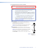
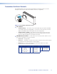
Transmitter fiber optic connectors and LEDs —
WARNING: These units output continuous invisible light, which may be harmful to
the eyes; use with caution. For additional safety, plug the attached dust
caps into the optical transceivers when the fiber cable is unplugged.
NOTES: • Ensure that you use the proper ber cable for your transmitter and
receiver pair. Typically, singlemode fiber has a yellow jacket and
multimode cable has an orange or aqua jacket.
• Only one fiber optic cable, transmitter-Tx-to-receiver-Rx, is required for
video, audio, and serial command transmission. But, if you connect only
one fiber optic cable, or if your receiver is configured to daisy-chain the
optical signal:
• The HDMI signal output by the receiver is not HDCP-compliant.
• You do not receive RS-232 reports from the controlled device.
To receive responses from the controlled device and for HDCP
compliance, you need to install both fiber optic cables and leave link 2
enabled (via an SIS command to the receiver or using the FOX
Extenders Control Program).
ä
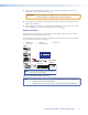
Tx (required) — For all one-way video, audio, and serial
communications from the transmitter to the receiver, connect a
fiber optic cable to the Tx LC connector.
Connect the free end of this fiber optic cable to the Rx connector
(item
ç
on the next page) on the PowerCage FOX Rx HDMI
receiver or to any other compatible Extron FOX device.
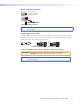
ã
Rx (optional) — Connect a fiber optic cable for all one-way
return serial communications from the receiver to the transmitter.
Connect the free end of this fiber optic cable to the Tx connector
(item
å
on the next page) on the PowerCage FOX Rx receiver in
normal mode or to any other compatible Extron FOX device.
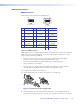
Tx and Rx LEDs — When lit, the link is active (light is received).
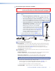
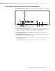
Figure 3. One Way
Configuration
Receiver
Transmitter
6a 6b
7b 7a
Tx Rx
Tx Rx
PowerCage FOX HDMI • Installation and Operation 7