
User Guide User guide

PowerCage Front Panel Port, Control, and Indicators
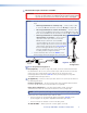
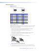
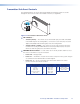
The following features are on the front panel of the PowerCage enclosure (see figure 12).
PowerCage 1600
COMM
1
POWER
ALARM
2 3 14 15 16
1
PSU
2
PSU
1
FAN
2
FAN
COMM
SELECT
CONFIG
TEMP
2 3 6541
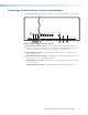
Figure 12. PowerCage Front Panel Features
a
Comm LED (16 board locations) — This LED lights to indicate that the board at this
location is selected for connection to the Configuration port (item
e
). Repeatedly press
the Comm Select button (item
d
) as necessary to select the desired board.
b
Power LED (all locations) — This LED lights to indicate that power is applied to the
device at this location.
c
Alarm LED (16 board locations) — This LED lights to indicate that light is not received
on the Rx connector of the board at this location.
Alarm LED (2 PS locations) — This LED lights to indicate that the power supply has failed
or is out of tolerance.
Alarm LED (2 Fan locations) — This LED lights to indicate that the fan has failed.
PowerCage FOX HDMI • Installation and Operation 14