User Guide PowerCage Products PowerCage™ MTP AV Series MTP Twisted Pair Transmitter and Receiver Modular Boards 68-1643-01 Rev.
Safety Instructions • English Warning This symbol is intended to alert the user of important operating and maintenance (servicing) instructions in the literature provided with the equipment. Power sources • This equipment should be operated only from the power source indicated on the product. This equipment is intended to be used with a main power system with a grounded (neutral) conductor. The third (grounding) pin is a safety feature, do not attempt to bypass or disable it.
FCC Class A Notice This equipment has been tested and found to comply with the limits for a Class A digital device, pursuant to part 15 of the FCC Rules. Operation is subject to the following two conditions: 1. This device may not cause harmful interference. 2. This device must accept any interference received, including interference that may cause undesired operation.
Contents Introduction............................................. 1 Reference Information............................ 8 About this Guide.............................................. 1 About the PowerCage MTP AV Transmitters and Receivers................................................... 1 Features............................................................ 2 Specifications.................................................... 8 Part Numbers..................................................
Introduction • About this Guide • About the PowerCage MTP AV Transmitters and Receivers • Features About this Guide This guide contains information about the following Extron® PowerCage™ MTP AV modular board-designed twisted pair transmitters and receivers that are compatible with the PowerCage Modular Power Enclosure: • PowerCage MTP T AV transmitter • PowerCage MTP R AV receiver This guide includes instructions for an experienced installer to install, configure, and operate the equipment.
Features • PowerCage MTP T AV transmits composite video or S-video along with summed mono audio signals 1,000 feet (300 meters) or more over a single CAT 5, 5e, 6, or Extron Enhanced Skew-Free™ UTP cable. • Compatible with NTSC, PAL, and SECAM • Modular, field-upgradeable, and hot-swappable boards are designed for the PowerCage 1600 enclosure.
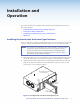
Installation and Operation This section describes the installation and operation of the PowerCage MTP T AV and MTP R AV, including: • Installing the Boards into the PowerCage Enclosure • Connections, LEDs, and Encoders • PowerCage Front Panel Port, Control, and Indicators • Operation Installing the Boards into the PowerCage Enclosure Up to 16 single slot or 8 dual slot input/output boards can be inserted into the PowerCage enclosure.
3. Carefully slide the board into the slot, aligning that the two tabs on the lower front end of the board with the matching ports in the enclosure. Push the board firmly into place. If the PowerCage is powered on, the power LED on the board lights. 4. Tighten the screws to secure the board in place. NOTE: Use a tool to fully tighten the screws after initial installation and subsequent removal and replacement of the boards.. 5. Repeat steps 2 though 4 for all boards needing installation.
NOTES: The length of exposed wires is critical. The ideal length is 3/16 inch (5 mm). If the stripped section of wire is longer than 3/16 inch, the exposed wires may touch, causing a short circuit. If it is shorter than 3/16 inch, wires can be easily pulled out of the captive screw connectors. Figure 5 identifies the tip, ring, and sleeve parts of standard audio connectors. A mono audio connector consists of the tip and sleeve. A stereo audio connector consists of the tip, ring and sleeve.
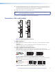
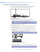
PowerCage Front Panel Port, Control, and Indicators For full details on the mounting, setup, and operation of the PowerCage 1600 enclosure refer to the PowerCage 1600 Enclosure User Guide, online at www.extron.com. The following features are on the front panel of the PowerCage enclosure. 1 2 3 14 15 16 COMM POWER ALARM PSU 1 PSU 2 FAN 1 FAN 2 COMM SELECT TEMP CONFIG PowerCage 1600 6 7 8 9 10 11 Figure 6.
k Temp LED — This LED lights to indicate that the temperature within the PowerCage enclosure is high (approximately 167 °F [75 °C]) and equipment damage is imminent. Operation After the transmitter, all receivers, and their connected devices are powered up, the system is fully operational. If any problems are encountered, verify that the cables are routed and connected properly, and that all display devices have suitable resolutions and refresh rates.
Reference Information This section provides the specifications and part numbers for the PowerCage MTP T AV and Powercage MTP R AV modular boards. • Specifications • Part Numbers Specifications NOTE: For PowerCage Enclosure specifications, refer to the PowerCage 1600 Enclosure User Guide, or to the PowerCage system specifications, available online at www.extron.com.
Audio input — PowerCage MTP T AV Number/signal type ������������������������ Connector �������������������������������������� Impedance ������������������������������������� Nominal levels �������������������������������� Maximum level ������������������������������� 1 stereo, unbalanced (1) 3.5 mm captive screw connector, 5 pole >10k ohms, unbalanced: >20k ohms, balanced: AC coupled +4 dBu (1.23 Vrms), -10 dBV (316 mVrms) +18 dBu, (unbalanced) at 1% THD+N NOTE: 0 dBu = 0.
Part Numbers PowerCage MTP AV Part Numbers The PowerCage MTP AV boards must be installed in a PowerCage 1600 enclosure. PowerCage Enclosure and Boards Part number PowerCage MTP T AV 70-815-01 PowerCage MTP R AV 70-816-01 Included Parts These items are included in each order for a PowerCage MTP T AV and MTP R AV: Included parts Part number IEC power cord Tweeker (small screwdriver) Setup guide Captive screw 5-pole connectors (qty.
Extron® Warranty Extron Electronics warrants this product against defects in materials and workmanship for a period of three years from the date of purchase.