User Guide PoleVault® Wallplates PVT Series PoleVault Twisted Pair Input Wallplates (Decora® and AAP models) PVT CV D, PVT RGB D Plus, PVT RGB D PVT CV AAP, and PVT RGB AAP 68-1259-01 Rev.
Precautions Safety Instructions • English Warning This symbol is intended to alert the user of important operating and maintenance (servicing) instructions in the literature provided with the equipment. Power sources • This equipment should be operated only from the power source indicated on the product. This equipment is intended to be used with a main power system with a grounded (neutral) conductor. The third (grounding) pin is a safety feature, do not attempt to bypass or disable it.
FCC Class A Notice This equipment has been tested and found to comply with the limits for a Class A digital device, pursuant to part 15 of the FCC Rules. Operation is subject to the following two conditions: 1. This device may not cause harmful interference. 2. This device must accept any interference received, including interference that may cause undesired operation.
Conventions Used in this Guide In this user guide, the following are used: WARNING: CAUTION: NOTE: A warning warns of things or actions that might cause injury, death, or other severe consequences. A caution indicates a potential hazard to equipment or data. A note draws attention to important information. Copyright © 2012 Extron Electronics. All rights reserved. Trademarks All trademarks mentioned in this guide are the properties of their respective owners.
Contents Introduction............................................. 1 About the PVT Input Wallplates........................ 1 Transmission distance.................................... 1 About the PVT CV D..................................... 2 About the PVT CV AAP................................. 2 About the PVT RGB D (EDID)......................... 3 About the PVT RGB D Plus (EDID).................. 3 About the PVT RGB AAP (EDID)..................... 3 Installation.........................................
PVT Series • Contents vi
Introduction The section discusses basic information as an introduction to the PVT Series of twisted pair AV input wallplates. This section covers the following: • About the PVT Input Wallplates About the PVT Input Wallplates The Extron PVT Series PoleVault® Twisted Pair Input Wallplates (Decora® and Architectural Adapter Plates [AAP] models) described in this guide are a series of five cost effective twisted pair transmitters.
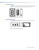
About the PVT CV D The PVT CV D is a wall or furniture mountable wall plate that fits any single opening Decora style wall plate. It can transmit composite video and stereo audio to any PoleVault switcher. In addition, a 2-pole IR pass-through provides control connection for IR devices. VIDEO IN VIDEO IN AUDIO IN L AUDIO IN L R R IR OUT IR OUT S G S G Figure 1.
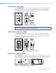
About the PVT RGB D (EDID) The PVT RGB D (EDID) is a wall or furniture mountable model that fits any single opening Decora style wall plate. It can transmit computer (RGB) video and stereo audio to the PVS switcher, and has an IR pass-though port to a provide control connection for DVD/VCR players, tuners, switchers, or other IR controllable devices. GS AUDIO IN AUDIO IN COMPUTER IN COMPUTER IN S G ON 1 2 3 4 5 S G IR OUT IR OUT RGB A RGB B OUT OUT Figure 3.
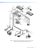
Extron FF 120 Flat Field Ceiling Speakers - 1 Pair Extron SPK 18 - 35' Extron Priority Page Sensor (Optional Accessory) Cable From PA system UTP Cable (CAT 5/5E/6) To PoleVault Switcher Ceiling Mounted Paging Speaker Extron PCM 340 Extron VoiceLift Receiver Projector Drop Ceiling Mount (Optional Accessory) Extron PVS 305SA Slotted Projector Mount Pole PoleVault® Switcher Extron PMK 550 Easy Installation Pole Mount Kit CON FIG 1 INPU 2 T SELE CTIO 3 N 4 5 INPUT AUX AUD IO AUD PEAK N
Installation The section discusses the method of installation, cabling, and using EDID Minder of the PVT series wallplates. This section covers the following: • UL Safety Requirements • Installing the Wallplates • Connections and Settings • EDID Minder UL Safety Requirements The Underwriters Laboratories (UL) requirements listed below pertain to the safe installation and operation of these devices. Important safety instructions 1. Read these instructions. 2. Keep these instructions. 3.
Installing the PVT CV and PVT RGB Decora models The PVT CV and PVT RGB Decora models can be installed into a wall using either the supplied mud ring or a UL approved one-gang electrical wall box, and finished with a Decora wall plate cover (supplied). The installation must conform to national and local electrical codes and to the wall plate size requirements. The following Underwriters Laboratories (UL) requirements pertain to the installation of the PVT input wallplates into a wall or furniture. 1.
To Install into a Wall Box Choose a location that allows cable runs without interference. Allow enough depth for both the wall box and the cables. The box should be at least 2.5 inches (6.4 cm) deep to accommodate the connectors and cables. Install the cables into the wall, furniture, or conduits before installing the wall plate. Follow the steps below 1. Feed cables for the output devices through the opening and through the wall box punch-out holes, securing them with cable clamps to provide strain relief.
5. For more detailed installation information, refer to the installation guide shipped with the device. NOTE: The PVT input wall plate should be cabled and tested before it is finally installed into the wall or device face plate. The rear panel connections will be inaccessible after installation. See Rear Panel - Features on page 11. 6. After testing and making any adjustments, turn off the power supply to the PoleVault switcher, and carefully secure the faceplate on the wall box device. 7.
Connections and Settings The section discusses the method of cabling and using EDID Minder for the PVT series wallplates. This section covers the following: • Front Panel Features • Rear Panel (Cabling and Features) • EDID Minder • Final Installation CAUTION: Do not connect these devices to a computer data or telecommunications network.
b Audio (left and right) input (CV D and CV AAP models) — For unbalanced left and right audio input, plug male RCA audio plugs into these two female RCA jacks (white = left, red = right). Tip (Signal) Right Channel (Red Jacket) Tip (+) Sleeve (Gnd ) Left Channel (White Jacket) Sleeve ( ) Figure 10. RCA audio connectors c Composite video input (CV D and CV AAP models) — To input a composite video signal from a suitable source, insert a male RCA plug into this yellow female RCA jack.
Rear Panel — Features All models have the output connectors on the rear panel. 2 PVT CV AAP 1 1 PVT CV D Figure 12. PVT CV models rear panel features a Composite video output (PVT CV models) — For composite video output, using CAT 5e or 6 UTP cable, connect this RJ-45 female video output port to one of the two composite video RJ-45 input connectors (labelled 3 and 4 video), on the rear panel of the PoleVault switcher.
Ö RGB B output (PVT RGB models) — Using CAT 5e or 6 UTP cable, connect this RJ-45 female output port labelled “RGB A out” to one of the input ports labelled B (for example, 2B) on the PoleVault switcher. NOTE: GS Cable A carries horizontal sync information and the red, green, and blue signals. Cable B primarily carries the audio signal, the vertical sync information, and 5 VDC to power the PVT transmitter.
EDID Minder The PVT RGB D (EDID), PVT RGB D Plus (EDID), and PVT RGB AAP (EDID) incorporates EDID Minder, which allows the transmitter to communicate the appropriate EDID information to the source, ensuring correct video output resolution. IN AUDIO OUT COMPUTER IN MONITOR OUT The 5-pole EDID Minder settings DIP switch is located on the rear of the wallplate. Once installed, these switch settings are only accessible by removing the device from its installed location.
Using Learn mode (available on PVT RGB D Plus only) 1. Disconnect any sources from the front panel and remove the wallplate from the wall. 2. On the rear panel, set all the DIP switches to off (down). 3. Temporarily connect the main display device (the projector) to the “Monitor Out” port. 4. On the front panel, the learn LED is lit solid green. Press and release the Learn button. IN AUDIO OUT COMPUTER IN EDID Learn Button EDID Learn Status LED MONITOR OUT S G IR OUT 5.
Reference Material This section provides information about: • Specifications • Part Numbers and Accessories Specifications PVT Series NOTE: These transmitters are compatible only with an Extron PoleVault® Switcher (PVS). They are not compatible with other models of twisted pair receivers.
Video input — composite video Number/signal type ������������������������ Connectors ������������������������������������ Nominal level ��������������������������������� Minimum/maximum levels �������������� Impedance ������������������������������������� Return loss ������������������������������������� DC offset (max. allowable) ������������� 1 composite video 1 female RCA 1 Vp-p for composite video Analog: 0.3 V to 1.
Enclosure type PVT CV D, PVT RGB D, PVT RGB D Plus Plastic All other models ���������������������� Metal Enclosure dimensions )PVT CV D, PVT RGB D and PVT RGB D Plus (including EDID models) Faceplate ��������������������������� 2.6" H x 1.3" W x 0.2" D (6.6 cm H x 3.3 cm W x 0.6 cm D) (Fits the openings in a 1 gang Decora® plate.) Device �������������������������������� 2.7" H x 1.7" W x 1.6" D (6.9 cm H x 4.3 cm W x 4.1 cm D) (Depth excludes connectors, height excludes mounting tabs.
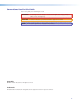
Part Numbers and Accessories PoleVault AV Input Plate Part Numbers Description Part Number PVT CV D 60-819-33 PVT RGB D 60-1066-03 PVT RGB D PLUS 60-1065-03 PVT CV AAP, black, white 70-579-12,13 PVT RGB AAP, black, white 70-722-02,03 Included Parts Items marked * are for PVT CV D, PVT RGB D, and PVT RGB D Plus models only.
PVT Series • Reference Material 19
Extron Warranty Extron Electronics warrants this product against defects in materials and workmanship for a period of three years from the date of purchase.