User’s Manual RAC 104 Remote Volume and Tone Controller 68-782-01 Rev.
Precautions Safety Instructions • English This symbol is intended to alert the user of important operating and maintenance (servicing) instructions in the literature provided with the equipment. This symbol is intended to alert the user of the presence of uninsulated dangerous voltage within the product's enclosure that may present a risk of electric shock. Caution Read Instructions • Read and understand all safety and operating instructions before using the equipment.
FCC Class A Notice This equipment has been tested and found to comply with the limits for a Class A digital device, pursuant to part 15 of the FCC Rules. These limits are designed to provide reasonable protection against harmful interference when the equipment is operated in a commercial environment. This equipment generates, uses and can radiate radio frequency energy and, if not installed and used in accordance with the instruction manual, may cause harmful interference to radio communications.
Table of Contents, cont’d ii RAC 104 • Table of Contents
Quick Start Guide — RAC 104 To install and set up the RAC 104 remote volume and tone controller, follow these steps and see the appropriate section of this manual for details: Step 1 Turn all of the equipment off and disconnect the power cords. Step 2 Mount the RAC 104 (if applicable) or affix the rubber feet to the bottom of the unit for tabletop use. See Projector Mounting Bracket Mounting Bolt A Tx Rx CON TRO LS ADJ UST MEN TS Vol.
Quick Start Guide — RAC 104, cont’d Step 4 If the RAC 104 is to be connected to a computer or host controller for remote control, connect the host’s RS-232 cable to the RAC 104’s 3-pole captive screw RS-232 connector. Wire the connector as shown below. See chapter 3 for more information on remote control.
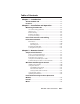
Table of Contents Chapter 1 • Introduction .......................................................... 1-1 About the RAC 104 ................................................................ 1-2 Features ...................................................................................... 1-2 Chapter 2 • Installation and Operation .......................... 2-1 Mounting the RAC 104 ........................................................ 2-2 UL rack mounting guidelines ......................................
Table of Contents, cont’d Appendix A • Specifications, Part Numbers, and Accessories .............................................................................. A-1 Specifications ......................................................................... A-2 Included Parts ......................................................................... A-4 Accessories ..............................................................................
RAC 104 1 Chapter One Introduction About the RAC 104 Features
Introduction About the RAC 104 The Extron RAC 104 is a high-performance, four-channel remote audio controller that adjusts volume and tone for stereo or mono audio signals. Adjustments are made via the RAC 104’s front panel controls or through a device connected to the unit’s RS-232 connector. The four channels on the RAC 104 can be used as four discrete mono channels or can be tied into pairs as stereo channels.
Consumer and professional audio compatibility — Input and output line level can be set to consumer (-10 dBV) or professional (+4 dBu). Rack, furniture, and projector mountability — The RAC 104 can be mounted on an optional VersaTools or Universal rack shelf. Alternatively, it can be mounted under a desk, podium, or other furniture, or secured to a projector mount with optional brackets.
Introduction, cont’d 1-4 RAC 104 • Introduction
RAC 104 2 Chapter Two Installation and Operation Mounting the RAC 104 Rear Panel Features and Cabling Front Panel Controls
Installation and Operation Mounting the RAC 104 The RAC 104 can be set on a table or mounted on a rack shelf, under a desk or tabletop, or on a projector mount. UL rack mounting guidelines The following Underwriters Laboratories (UL) guidelines pertain to the safe installation of the RAC 104 in a rack. 2-2 1.
Tabletop use Four self-adhesive rubber feet are included with the RAC 104. For tabletop use, attach one foot at each corner of the bottom side of the unit and place the unit in the desired location. Rack mounting For optional rack mounting, do not install the rubber feet. Mount the RAC 104 on an RSF 123 VersaTools™ 19" 1U rack shelf (Extron part #60-190-20) or a RSU 129 universal 1U rack shelf (Extron part #60-190-01).
Installation and Operation, cont’d Furniture mounting Furniture mount the RAC 104 using the optional MBU 123 mounting kit (Extron part #70-212-01) as follows: 1. Remove rubber feet if they were previously installed on the bottom of the RAC 104. 2. Attach the furniture mounting brackets to the RAC 104 with the machine screws provided. 3. Hold the RAC 104 with the attached brackets against the underside of the table or other furniture.
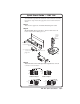
Projector mounting Projector mount the RAC 104 using the optional PMK 100 pole mount kit (part #70-217-01) as follows: 1. Remove rubber feet if they were previously installed on the bottom of the RAC 104. 2. Attach the projector mounting brackets to the RAC 104 with the machine screws provided. 3. Secure the RAC 104 to a projector mount or other surface by inserting the mounting bolt through the bracket’s slotted hole, as shown below.
Installation and Operation, cont’d Rear Panel Features and Cabling 1 INPUTS RAC 104 POWER IN 12V 0.2A MAX 1 A 2 3 B 4 1 A 2 3 B 4 OUT A B A B ON Tx Rx +4 dBu 5 3 -10 dBV LINE LEVEL OUTPUTS 4 1 2 Input connectors — Plug the audio input devices into these two 5-pole captive screw connectors. One stereo device or two mono devices can be connected to each captive screw connector. Wire the connectors as shown below.
RS-232 connector — Plug an optional RS-232 device into this 3-pole captive screw connector. Wire the connector as shown below. 3 Tx Rx RS-232 Transmit (Tx) Receive (Rx) Ground (Gnd, ) Pin RS-232 function Description 1 2 3 Tx Rx Gnd Transmit data Receive data Signal ground Line level selector DIP switches — Set these switches to -10 dBV (unbalanced, consumer line level) or +4 dBu (balanced, professional line level). There are four switches, one for each input group and output group.
Installation and Operation, cont’d Your RAC 104 may have shipped with a blue captive screw connector. This blue connector can be plugged into either a blue or an orange power receptacle. The ideal length of exposed (stripped) copper wire for the blue connector is 3/16" (5 mm). The blue connector does not have the extended tail or the included tie-wrap. Do not tin the power supply leads before installing in the direct insertion connector.
Front Panel Controls AUDIO CONTROLS A ADJUSTMENTS B VOL 1 3 BASS 2 4 TREBLE RAC 104 VOLUME & TONE CONTROLLER 1 2 3 4 1 Power LED — Lights to indicate that the RAC 104 is on. 2 Channel selector buttons and LEDs — The RAC 104 has two channel selector buttons, one for channel group A (channels 1 and 2) and one for channel group B (channels 3 and 4). Press and release these buttons to select the channel(s) to adjust. When a channel is selected, the corresponding LED lights.
Installation and Operation, cont’d 3 Adjustment selector button and LEDs — Press and release this button to select volume, bass, or treble adjustment. When an adjustment is selected, the corresponding LED lights. If after 10 seconds you do not make any other adjustments or selections on the front panel, this selector will default to volume. The adjustment selector button will not function unless you have first selected one or more channels (see 2 , above).
For example, if the treble on channel 1 is set to 6 and the treble on channel 2 is set to 10, the unit will change channel 2’s treble setting to 6 when the user ties them together. Treble before tie: Treble after tie: Channel 1 Channel 2 6 10 6 6 Volume, bass, treble, and mute adjustments can now be made to both channels simultaneously.
Installation and Operation, cont’d 2-12 RAC 104 • Installation and Operation
RAC 104 3 Chapter Three Remote Control Simple Instruction Set Windows-Based Program Control Front Panel Security Lock Out (Executive Modes) Presets Mute
Remote Control The RAC 104 can be controlled remotely via the RS-232 connector using the Extron Simple Instruction Set (SIS) or the Extron Windows-based control program. The RS-232 connector on the RAC 104 is a 3-pole captive screw connector, with one pole for transmitting data, one for receiving data, and one for the ground. Wire the RS-232 connector as shown below.
Controller error responses When the RAC 104 receives an SIS command and determines that it is valid, it performs the command and sends a response to the host device. If the controller is unable to perform the command because the command is invalid or contains invalid parameters, the contoller returns an error response to the host. The error response codes are: E01 — Invalid channel number (too large) E10 — Invalid command E13 — Invalid value (out of range) E14 — Invalid setting at this time (i.e.
Remote Control, cont’d 3 = group B, channel 3 4 = group B, channel 4 X3 = 0 or 1 0 = off 1 = on X4 = 0 through 14, bass adjustment range (+/-14 dB; 2 dB increment/decrement, bass in dB = [bass number minus 7] times 2; default = 7 [0 dB]). X5 = 0 through 14, treble adjustment range (+/-14 dB; 2 dB increment/decrement, treble in dB = [treble number minus 7] times 2; default = 7 [0 dB]).
RAC 104 • Remote Control 3-5 Vol X2 * X1 Vol X2 * X1 Vol X2 * X1 X1 X2 V/v X3 X2 *0Z/z X2 Z/z 1*Z/z 0*Z/z Z/z Z View mute status of one channel Mute all channels Unmute all channels View mute status of all channels Example: Amt All* X3 Amt All* X3 X3 • X3 • X3 • X3 1010 Amt X2 * X3 Amt X2 * X3 X2 *1Z/z X2 -V/v X2 +V/v X2 * X1 V/v Mute one channel Unmute one channel Mute Specify volume level Increment volume Decrement volume View volume Output Volume X10 Gain Chn X2 Gain X10 Chn X2 X2 +G/
3-6 RAC 104 • Remote Control View preset status Example Save preset Recall preset Preset save and recall Specify treble level Increment treble level Decrement treble level View treble level Treble adjustment Specify bass level Increment bass level Decrement bass level View bass level Bass adjustment Command Bas X4 Bas X4 . Spr X2 * X9 Rpr X2 * X9 X3 • X3 • X3 011 X2 to X4 . X2 to X5 . Save preset X9 for channel X2 . Recall preset X9 for channel X2 .
RAC 104 • Remote Control 3-7 Upload firmware update Upload success Update firmware Reset to factory defaults System reset View input gain View output volume View bass setting View treble setting View Preset Settings Command Go UPL See note below. See note below. Default settings: Input gain X10 = 0 Volume level X1 = 70 Bass level X4 = 7 Treble level X5 = 7. Additional description Firmware updates will periodically become available on the Extron Web site.
3-8 RAC 104 • Remote Control X6 GrpA* X3 GrpB* X3 4# View ties of all groups Tie channels in group X8 together (0 = not tied, 1= tied). Group A tied/not tied, group B tied/not tied. View DIP switch settings (see table on page 3-4). 60-561-01. 0 = off. 1 = mode 1 (all features except volume are locked). 2 = mode 2 (all features are locked). 0 = off. 1 = mode 1. 2 = mode 2. Additional description Commands can be made back-to-back with no spaces. Example 1*1!02!03*03!..
RAC 104 • Remote Control 3-9 View treble upper limit View bass upper limit Set treble lower limit Set treble upper limit View treble lower limit Set volume lower limit Set volume upper limit View volume lower limit View volume upper limit Set bass lower limit Set bass upper limit View bass lower limit X2 X2 X2 X2 X2 X2 X2 X2 X2 X2 X2 X2 * * X1 X1 X5 X5 Tll X2 * X5 Tul X2 * X5 X4 X4 Bll X2 * X4 Bul X2 * X4 X1 X1 Vll Vul * 21 # * X1 * 22 # * 21 # * 22 # * X4 * 23 # * X4 * 24 # *
Remote Control, cont’d Windows®-Based Program Control The Windows-based Extron Audio Products Control Program is compatible with Windows 2000 and Windows XP and provides remote control of the volume, gain, and tone adjustment, and other RAC 104 features. Updates to this program can be downloaded from the Extron Web site (http://www.extron.com). Installing the software The program is contained on the Extron Software Products CD-ROM. To install the software: 1. Insert the CD-ROM into the drive.
Input/Output Level fields The Input Level and Output Level fields display the current settings for the line level selector DIP switches. See the chapter 2 section, “Rear Panel Features and Cabling”, for more information. Input/Output Level fields Preset Preview button To view a preset before recalling it, select a channel and preset number, then click and hold the Preview button.
Remote Control, cont’d Using the help system For information about program features, you can access the help program in any of the following ways: • From the Extron Electronics program group, double-click the Audio Products Help icon. • From within the Audio Products Control program, click Help on the task bar. • From within the Audio Products Control program, press the F1 key. Updating the firmware Firmware updates will periodically become available on the Extron Web site.
Front Panel Security Lockout (Executive Modes) To prevent accidental changes to the controller settings, the front panel controls can be locked using one of two executive modes. The user turns the executive modes on and off using either the SIS or the Windows-based control program via the RS-232 connector. While an executive mode is on, the locked controls can be adjusted through the RS-232 device only. Executive mode 1 locks the tone controls and channel selector buttons only.
Remote Control, cont’d 3-14 RAC 104 • Remote Control
RAC 104 A Appendix A Specifications, Part Numbers, and Accessories Specifications Included Parts Accessories
Specifications, Part Numbers, and Accessories Specifications Audio Gain ................................................ Unbalanced output: -6 dB; balanced output: 0 dB when input gain is set to 0 dB, output volume is at 100, and the input and output are set to the same level via the Line Level DIP switch Frequency response .................... 20 Hz to 20 kHz, ±0.05 dB THD + Noise ................................. 0.03% @ 1 kHz at nominal level S/N ...............................................
Input gain adjustment ................. –12 dB to +12 dB 0 dBu = 0.775 Vrms, 0 dBV = 1 Vrms, 0 dBV 2 dBu. Audio output Number/signal type ................... 4 channels, which can be mono or tied into stereo pairs, balanced/unbalanced Connectors ................................... (2) 3.5 mm captive screw connector, 5 pole Impedance .................................... 50 ohms unbalanced, 100 ohms balanced Nominal level ............................... +4 dBu (1.
Specifications, Part Numbers, Accessories, cont’d Enclosure dimensions ................. 1.7" H x 4.3" W x 3.0" D (1U high, quarter rack wide) 4.3 cm H x 10.9 cm W x 7.6 cm D (Depth excludes connectors and knob.) Product weight ............................. 0.5 lbs (0.3 kg) Shipping weight ........................... 2 lbs (1 kg) Vibration ....................................... ISTA 1A in carton (International Safe Transit Association) Regulatory compliance Safety .................................
Extron’s Warranty Extron Electronics warrants this product against defects in materials and workmanship for a period of three years from the date of purchase.
Extron USA - West Headquarters +800.633.9876 Inside USA / Canada Only +1.714.491.1500 +1.714.491.1517 FAX Extron USA - East Extron Europe Extron Asia Extron Japan Extron China Extron Middle East +800.633.9876 +800.3987.6673 +800.7339.8766 +81.3.3511.7655 +81.3.3511.7656 FAX +400.883.1568 +971.4.2991800 +971.4.2991880 FAX +1.919.863.1794 +1.919.863.1797 FAX +31.33.453.4040 +31.33.453.4050 FAX +65.6383.4400 +65.6383.