User’s Manual RGB 138xi , RGB 168xi VGA Interfaces with Stereo Audio and ADSP™ Extron Electronics, USA 1230 South Lewis Street, Anaheim, CA 92805 800.633.9876 714.491.1500 FAX 714.491.1517 USA Extron Electronics, Europe Beeldschermweg 6C, 3821 AH Amersfoort +31.33.453.4040 FAX +31.33.453.4050 The Netherlands Extron Electronics, Asia 135 Joo Seng Rd. #04-01, PM Industrial Bldg. +65.383.4400 FAX +65.383.4664 Singapore 368363 © 2001 Extron Electronics. All rights reserved.
Precautions Safety Instructions • English This symbol is intended to alert the user of important operating and maintenance (servicing) instructions in the literature provided with the equipment. This symbol is intended to alert the user of the presence of uninsulated dangerous voltage within the product's enclosure that may present a risk of electric shock. Caution Read Instructions • Read and understand all safety and operating instructions before using the equipment.
Table of Contents Chapter 1 • Introduction .......................................................... 1-1 About this Manual ................................................................ 1-2 xi and RGB 168xi xi ............................. 1-2 About the RGB 138xi Features ...................................................................................... 1-2 RGB 138xi and RGB 168xi features ........................................ 1-2 RGB 138xi features ................................................
Table of Contents, cont’d xi RGB 138xi xi, RGB 168xi xi 1 Chapter One Introduction About This Manual About the RGB 138xi and RGB 168xi Features ii xi Table of Contents RGB 138xi xi, RGB 168xi xi xi Introduction RGB 138xi xi, RGB 168xi xi
Introduction, cont’d Introduction About This Manual This manual contains information about the RGB 138xi and RGB 168xi universal analog interfaces and on how to operate and configure them. Unless otherwise specified, references to “the interface” refer to the features or operation of both models. xi About the RGB 138xi xi and RGB 168xi The RGB 138xi and RGB 168xi are computer-video and stereo audio interfaces with 300 MHz (-3dB) video bandwidth.
Introduction, cont’d xi RGB 138xi xi, RGB 168xi xi 2 Chapter Two Installation and Operation Installation Overview Front Panels Rear Panels Setting Internal Jumpers Installing Adapter Plates Mounting the Interfaces Cabling Troubleshooting 1-4 xi Introduction RGB 138xi xi, RGB 168xi xi xi Installation and Operation RGB 138xi xi, RGB 168xi xi
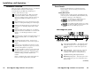
Installation and Operation, cont’d Installation and Operation Installation Overview Front Panels This is an overview of the installation process. You will find detailed installation instructions in this chapter. This section will familiarize you with the front panel features and the options for making connections and changing settings.
Installation and Operation, cont’d Horizontal shift control knob — This control adjusts the horizontal centering of the remote output display. 3 Analog video input 15-pin HD female connector 4 ID bit termination DIP switches — These switches provide proper ID bit termination when a local monitor is not connected to the interface’s buffered local monitor output. ID PIN 4 ID PIN 11 5 The horizontal and vertical shift controls have no mechanical limits to rotation.
Installation and Operation, cont’d Rear Panels If the edges of the image seem to exceed their boundaries or if thin lines and sharp edges look thick and fuzzy, try changing the gain/peak setting. xi rear panel RGB 138xi xi and RGB 168xi GAIN/ PEAK 100% SOG DDSP SERR SPARE DIP switch 4 controls input termination in the RGB 138xi and is a spare in the RGB 168xi.* R G B H V S UNITY 100-240 50/60 Hz 0.
Installation and Operation, cont’d properly. Flagging or bending at the top of the video image is a sign that the serration pulses should be removed. ON — When this switch is set to On, serration pulses will be output in the vertical sync interval. OFF — When this switch is set to Off, serration pulses will not be output.
Installation and Operation, cont’d 3. Note the positions of jumpers J20 and J40 before changing jumper settings. The illustration of the circuit board (below) shows the locations of the J20 and J40 jumpers. There are two possible setting combinations for 3-pin jumpers: Follow J-20: Sync polarity jumper — This jumper adjusts the output sync polarity. Horizontal (H) and vertical (V) sync output can either follow input sync Negative polarity, or be forced to negative.
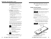
Installation and Operation, cont’d Adapter plates should be attached to the output cables and interface before the interface is installed in a rack or in furniture. The screws for installing the adapter plates are built into the plates, so no additional screws will be needed. Cable Routing ED ITCH SW UN Adapter plate installation must be performed by authorized service personnel only. TS WAT 600 Follow these steps to install adapter plates.
Installation and Operation, cont’d Through-desk mounting Mounting the Interfaces Select the installation site. Take cabling and power availability into consideration. Select an installation option: tabletop/desktop placement, or under-desk, through-desk or rack mounting. Tabletop/desktop placement For tabletop or desktop placement only, install the selfadhesive rubber feet/pads (provided) onto the four corners of the bottom of the interface enclosure. Under-desk mounting 1.
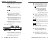
Installation and Operation, cont’d Rack mounting Cabling 1. Attach the through-desk/rack mounting brackets to the interface with the provided machine screws, as shown below. Attach cables to the interface as detailed in the steps below. A diagram later in this section shows how the system looks when cabling is finished. 2. Attach the interface to the rack with the provided machine screws. 1. Connect the computer’s video output to the interface’s front panel analog/ECL 9-pin D connector.
Installation and Operation, cont’d step 1 to connect the computer to the interface. Set the front panel monitor ID bit DIP switches to On if no local monitor will be used. AC Power HE UN SW D ITC X. MA Mounted under a Desk 600 TTS WA 8 xi B 13/ADSP RGACE W ERF X /MA L INT MIN RSA IVE UN Network Connection C MB G UTS INP ANALO ER POW IO AUD Front L/ LEVEK PEA 50% 0.8V Audio SOG OUT DDSP SERR SPARE 5.
Installation and Operation, cont’d Troubleshooting When the interface, computer and output devices have been properly installed, and the power is turned on, the image should appear on screen, and sound should be audible. If the image does not appear or there is no sound 1. Ensure that all devices are plugged in. 2. Make sure that each device is receiving power. The power indicator LED should light if the interface is powered on. 3.
Specifications, cont’d Specifications Video Gain ................................................ Unity, (0.725V p-p) 50% peaking, (0.75V pp) 100% peaking Bandwidth ..................................... 300 MHz (-3dB) Video input Number/signal type ................... 1 analog RGBHV, RGBS, RGsB, RsGsBs Connectors ................................... RGB 138xi .................. 1 9-pin D male, MBC/LBC cable or buffer RGB 168xi ..................... 1 15-pin HD female Minimum/maximum levels ....... Analog ..
Specifications, cont’d Enclosure type .............................. Metal Enclosure dimensions ................. 1.75" H x 17.5" W x 6" D 4.5 cm H x 44.5 cm W x 15.2 cm D (Depth excludes connectors and knobs. Width excludes rack ears.) Shipping weight ........................... 7 lbs (3.2 kg) Vibration ....................................... ISTA/NSTA 1A in carton (International Safe Transit Association) Approvals ..................................... UL, CE, FCC Class A MTBF .............................
Accessories and Part Numbers, cont’d Accessories and Part Numbers Included Parts Laptop breakout cables* These items are included in each order for an RGB 138xi or RGB 168xi : (RGB 138xi )Part number LBC VGA HR 6’ 26-244-01 LBC Mac HR 6’ 26-363-01 Part number LBC Sun HR 6’ A (61 kHz) (w/audio) 26-443-02 RGB 138xi 60-292-01 LBC Sun HR 6’ A (71 kHz) (w/audio) 26-444-02 RGB 138xi (Europe) 60-292-02 LBC Sun HR 6’ A (81 kHz) (w/audio) 26-445-02 RGB 168xi 60-379-01 *Laptop breakout cables ar
1 - 3-pin XLR Connector 2 - 3.5mm Stereo Mini Architectural adapter plates B-4 xi Accessories and Part Numbers RGB 138xi xi, RGB 168xi xi -03 -02 -01 70-109 RCA female and 3 solder cups RCA female and 3.5mm mini stereo jack -22 -12 -02 70-108 BNC female and 3 solder cups BNC female and 3.
xi Accessories and Part Numbers RGB 138xi xi, RGB 168xi xi xi Accessories and Part Numbers RGB 138xi xi, RGB 168xi xi B-7 Adapter plate description Plate size Front connector type Rear connector type Part # Gray Blank plate 1 1 n.a. n.a. 70-090 -01 -11 -21 Blank plate 2 2 n.a. n.a.
Accessories and Part Numbers, cont’d B-8 xi Accessories and Part Numbers RGB 138xi xi, RGB 168xi xi