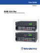
User Guide Interfaces RGB 203 Rxi Three Input, Universal Computer-Video Interface 68-655-01 Rev.
Precautions Safety Instructions • English Warning This symbol is intended to alert the user of important operating and maintenance (servicing) instructions in the literature provided with the equipment. Power sources • This equipment should be operated only from the power source indicated on the product. This equipment is intended to be used with a main power system with a grounded (neutral) conductor. The third (grounding) pin is a safety feature, do not attempt to bypass or disable it.
FCC Class B Notice This equipment has been tested and found to comply with the limits for a Class B digital device, pursuant to part 15 of the FCC Rules. These limits are designed to provide reasonable protection against harmful interference in a residential installation. This equipment generates, uses and can radiate radio frequency energy and, if not installed and used in accordance with the instructions, may cause harmful interference to radio communications.
Contents Introduction............................................. 1 About the RGB 203 Rxi..................................... 1 Features............................................................ 2 Rear Panel Cabling...................................................... 3 Rear Panel Connections.................................... 3 Configuration........................................... 6 Internal Configuration...................................... 6 Sync Polarity Jumpers..............................
RGB 203 Rxi • Contents vi
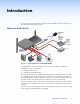
Introduction This user guide contains information about the Extron RGB 203 Rxi universal interface and how to operate and configure the unit.
Features EDID Minder — The Extron EDID Minder ensures the resolution of the video source signals is compatible with the display devices. Sync processing — Using regular sync processing to allow centering control (H-shift or V-shift) can create problems with some digital display devices as a result of the sync delay. The Extron ADSP option maintains a stable sync signal while allowing centering control.
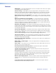
Rear Panel Cabling This section describes the rear panel cabling of the RGB 203 Rxi. The rear panels of both models are identical. Rear Panel Connections 2 100-240 3 2 INPUT 3 INPUT 1 0.2A INPUT 2 1 2 Figure 2.
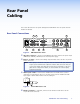
e BNC output connectors — Connect a coaxial cable between the display (projector or monitor) and the rear panel BNC connectors, as shown in the figure at right. For RGBHV (separate H and V sync) output, connect the cables to five BNCs. R G B H V S RGBHV For RGBS (composite sync), connect the cables to four BNCs. R G B H V S RGBS For RGsB (sync on green, SOG), connect the cables to three BNCs. Also select the SOG option on the rear panel DIP switch (see “Rear Panel DIP Switches” on page 8).
g Audio output connector — Connect an audio device, such as powered speakers, to this 3.5 mm, 5-pole captive screw connector for balanced or unbalanced audio output. The connector, but not the wires, are provided. Insert the wires into the correct openings and tighten the screws to fasten the wires (see figure 5). CAUTION: For unbalanced audio, connect the sleeves to the center contact ground. DO NOT connect the sleeves to the negative (-) contacts. Figure 5.
Configuration This section of the user guide provides information about internal configuration of jumpers on the circuit boards and configuration of the rear panel DIP switches. Internal Configuration The interface is factory configured to output RGBHV or RGBS video with sync that follows the input and is clamped to the back porch. The interface can be configured to output positive or negative sync or to clamp on the sync tip. These reconfigurations all require the interface to be opened. 1.
3. Configure the interface as desired (see “Sync Polarity Jumpers” and “Video Clamping Jumper” below). Figure 7 shows all of the user‑serviceable components. Rear J7 V Sync J6 H Sync J20 Enable Sync J11 3 2 1 1 1 J28 J23 RS-232 Connector Figure 7. J27 RGB 203 Rxi Internal Jumper Locations 4. Replace the cover and reinstall the screws. Sync Polarity Jumpers The interface is factory configured for the output sync to follow the input sync.
Rear Panel DIP Switches 100-240 INPUT 3 INPUT 1 0.2A INPUT 2 50/60 Hz AUDIO R G B V S REMOTE DDSP SOG SERR V SYNC WIDTH MONITOR FOLLOWS MONO AUDIO LEFT AUTO SWITCH NO BACK LIGHT AUDIO H OUTPUTS MONITOR L/MONO R 1 Figure 8. RGB 203 Rxi Rear Panel NOTE: a The default for all DIP switches is Off (down). DIP switches — This bank of DIP switches is used to configure the interface. The switches control: 1. DDSP or ADSP — DDSP disables all sync processing.
5. Monitor follows This switch controls the input assigned to the local monitor output and ID bit termination. On — The local monitor connector follows the input selection and ID bits 4 and 11 are tied to ground. Off — The local monitor output connector is locked to input 1 and ID bits 4 and 11 are unterminated. 6. Mono audio left On — Mono audio is output in the left channel only. Off — Output is normal stereo audio. 7.
Operation This section of the guide provides information about RGB 203 Rxi front panel controls and indicators and troubleshooting. Once the video and audio cables have been connected, the power cords have been connected, the internal jumpers configured (if necessary), and all devices powered on, the system is ready for operation. Select an input using the front panel toggle switch (i in figure 9) or the remote control device.
Select a setting in the boost range (0.7 volts and above) to compensate for the decrease in signal level that occurs when the signal passes through long cables. Set the boost at 100% (the maximum level) for cable lengths over 500 feet for all computer signals of 15 kHz to 150 kHz. b Peaking (Peak) control — Peaking affects the sharpness of a picture. Increased peaking can compensate for detail (mid- and high-frequency) loss from low bandwidth system components or capacitance in long cables.
EDID Minder Controls Video sources communicate with the output device through the bi-directional Extended Display Identification Data (EDID) communication protocol. The output device then produces a signal with a resolution that is compatible with the display device.
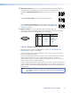
f 2 position DIP switch — The first DIP switch allows the user to choose the vertical frequency for the pre-programmed EDID, positions 1 to E on the rotary switch. The up position, which should be used in Europe, sets the vertical frequency to 50 Hz; the down position, which is the default setting, sets the vertical frequency to 60 Hz. 50 Hz 60 Hz SPARE The second DIP switch is not used by this device.
Using user-recorded EDID information Position 0 uses the EDID information that has been saved by the user (see “Record EDID Information” on the page 12). To use this information: 1. Connect the RGB 203 Rxi to the source. Do not switch on the source device yet. 2. Set the rotary switch to 0. 3. Power on the source device. NOTE: By default, setting 0 on the rotary switch has no EDID information saved to it. The user must save EDID to this location before it can be used.
LCD Display h LCD display — The LCD displays the horizontal and vertical scanning rates of the input signal, and indicates the horizontal and vertical centering status and limits. LCD screen backlight The LCD lights for 15 seconds at power-up and it remains lit as long as an input signal is present at the selected input. To force the backlight to remain off at all times except at power-up, set DIP switch 8 (No Backlight) to On (up) (see Rear Panel DIP Switches on page 8).
Input Selection i Input selection switch — The input selection toggle switch selects among inputs 1, 2, and 3 (see figure below). Each time you move the switch down, the interface switches to the next lower input (in the order that the inputs are listed on the front panel): input 1 input 2, input 2 input 3, input 3 input 1. Moving the switch up selects the next higher input (in the order that the inputs are listed on the front panel). The switch returns to the center position automatically.
Contact Closure Remote Control The rear panel Remote connector also provides a way to select an input to the interface using a remote contact closure device. Contact closure control uses pins on the Remote connector that are not used by the RS-232 interface. The contact closure pin assignments are shown in the table in figure 4. To select a different input number using a contact closure device, momentarily short the pin for the desired input number to logic ground (pin 5).
If the Image is Not Displayed Correctly 1. If the output image looks too green, the sync on green (SOG) DIP switch (switch 2) may be set to On (up), and the display device may not be configured to handle SOG signals. Set the switch to Off (down). 2. If the picture bends or flags at the top of the screen, set the serration pulse DIP switch (switch 3) to Off (down). 3. For a display device that experiences intermittent glitches, try changing the DDSP setting using DIP switch 1. 4.
If the Interface Does Not Record EDID 1. Make sure you have a display device connected to the local output. 2. Make sure the rotary switch is set to 0. 3. Make sure the LED flashes red slowly three times while the EDID information is stored and returns to a solid green when the recording is completed. 4. Check Record EDID Information on page 12 and Using User-Recorded EDID Information on page 14. NOTE: EDID information must be available to the source device as it boots up.
Specifications Video Routing ������������������������������������������ Gain ����������������������������������������������� Bandwidth ������������������������������������� Rise time ���������������������������������������� EDID ����������������������������������������������� 3 x 1 router 0.5 V to 1.45 Vp-p 300 MHz (-3 dB) 1.
S/N ������������������������������������������������� >90 dB at rated maximum output (17 dBu), balanced (unweighted) Crosstalk ���������������������������������������� <-90 dB @ 1 kHz, fully loaded Stereo channel separation �������������� >90 dB @ 1 kHz Audio input Number/signal type ������������������������ Connectors ������������������������������������ Impedance ������������������������������������� Nominal level ��������������������������������� Maximum level ������������������������������� NOTE: 2 PC
Reference Information This section provides information about included parts and optional accessories. Included Parts Description Part Number RGB 203 Rxi with ADSP or RGB 203 Rxi with EDID Minder 60-508-01 60-508-02 IEC cord (1) 5-pole captive screw connector 100-457-01 Rubber feet (4) Disc with control software Tweeker RGB 203 Rxi Setup Guide Optional Accessories Description Part Number RSU 129 1U, 9.5 inch deep, universal rack kit 60-190-01 RSB 129 1U, 9.
Control Software Control Software for Windows® The RGB 203 Rxi can be controlled by SIS™ commands (see page 24) or by the control software, which is on the DVD that shipped with the unit. The control software is also available for download from the Extron website (www.extron.com). Installing the Software The control software is compatible with Windows 3.1, 3.11, 95/98, and above. To install the software, follow these instructions: 1. Insert the provided disc into the DVD drive of the computer.
SIS Commands This section shows how to control the RGB 203 Rxi with Extron Simple Instruction Set (SIS) commands. The RS-232 protocol is 9600 baud, 1 stop bit, no parity, and no flow control. Connecting the Control Computer The rear panel Remote connector on the interface can be connected to the serial port of a computer or control system, or to a remote contact closure device.
Error Responses When the interface receives a valid SIS command, it executes the command and sends a response to the host device. If the interface is unable to execute the command because the command is invalid or it contains invalid parameters, it returns an error response to the host.
Command and Response Table for SIS Commands Command ASCII Command (host to unit) Response (unit to host) Additional Description X!! 3! ChnX!] Chn3] Select input X!. X! = 1, 2, or 3. Select input 3. Set horizontal shift X@H HphX@] Example: 28H Hph+028] Set horizontal shift value to X@. Shift control ranges from -127 to +127. Set horizontal shift value to +28. Increment horizontal shift value +H HphX@] Increases horizontal shift value by 1.
Mounting This section shows how to mount the RGB 203 Rxi. Options include: zz Tabletop mounting zz Under-desk mounting zz Through-desk mounting zz Rack mounting Follow the appropriate procedures in this section and in the instructions that come with the mounting kits. These instructions can also be downloaded from the Extron website (www.extron.com).
Rack Mounting UL Guidelines for Rack Mounting The following Underwriters Laboratories (UL) guidelines are relevant to the safe installation of these products in a rack: 1. Elevated operating ambient temperature — If the unit is installed in a closed or multi-unit rack assembly, the operating ambient temperature of the rack environment may be greater than room ambient temperature.
Extron® Warranty Extron Electronics warrants this product against defects in materials and workmanship for a period of three years from the date of purchase.
Extron USA - West Extron USA - East Extron Europe Extron Asia Extron Japan Extron China Extron Middle East +800.633.9876 Inside USA/Canada Only +800.633.9876 Inside USA/Canada Only +800.3987.6673 Inside Europe Only +800.7339.8766 Inside Asia Only +81.3.3511.7655 +81.3.3511.7656 FAX +400.883.1568 Inside China Only +971.4.2991800 +971.4.2991880 FAX +1.714.491.1500 +1.714.491.1517 FAX +1.919.863.1794 +1.919.863.1797 FAX +31.33.453.4040 +31.33.453.4050 FAX +65.6383.4400 +65.6383.