RGB 400xi Series Installation Guide www.extron.com Extron Electronics, USA Extron Electronics, Europe Extron Electronics, Asia Extron Electronics, Japan 1230 South Lewis Street Anaheim, CA 92805 USA 714.491.1500 Fax 714.491.1517 Beeldschermweg 6C 3821 AH Amersfoort The Netherlands +31.33.453.4040 Fax +31.33.453.4050 135 Joo Seng Road, #04-01 PM Industrial Building Singapore 368363 +65.6383.4400 Fax +65.6383.4664 Daisan DMJ Building 6F 3-9-1 Kudan Minami Chiyoda-ku, Tokyo 102-0074 Japan +81.3.3511.
Precautions Safety Instructions • English This symbol is intended to alert the user of important operating and maintenance (servicing) instructions in the literature provided with the equipment. This symbol is intended to alert the user of the presence of uninsulated dangerous voltage within the product's enclosure that may present a risk of electric shock. Caution Read Instructions • Read and understand all safety and operating instructions before using the equipment.
Table of Contents About this Guide ....................................................................... 1 Installation Overview ............................................................. 1 UL Requirements ....................................................................... 2 Installation Procedures .......................................................... 2 Preparing the site and installing the wall box ....................... 3 Mounting the interface to the wall box ..............................
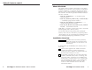
Table of Contents, cont’d About this Guide This guide contains installation information for the Extron RGB 400 Series of interfaces. These interfaces are designed to fit into standard 2-, 3-, and 4-gang electrical wall boxes. The EC versions of these interfaces are designed to fit into a Euro Channel. The following models will fit the indicated wall box or channel: • RGB 460xi and RGB 472xi* – A standard, 2-gang electrical wall box.
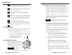
Introduction 3 4 Attach the cables. See “Front panel features and cabling” and “Rear panel features and cabling” in the user’s manual specific to your product. Set the rear panel DIP switches. Use the “Rear panel features and cabling” section in the user ’s manual specific to your product. 5 Connect power cords and turn on the projector/ monitor and audio device, the interface, and the computer. 6 The picture should now appear, and sound should be audible.
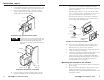
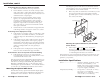
Installation, cont’d 5. Feed cables through the wall box punch-out holes, and secure them with cable clamps to provide strain relief. 6. Exposed cable shields (braids or foil) are potential sources of short circuits. Trim back and/or insulate shields with heat shrink, if needed. nails or screws, leaving the front edge flush with the outer wall or furniture surface. The illustration applies to all sizes of wall boxes. If attaching the wall box to wood, use four #8 or #10 screws or 10-penny nails.
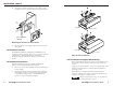
Installation, cont’d 3. Mount the interface’s faceplate to the wall box with machine screws, as shown in the following illustration. H. SH IFT /M AX B G DIO R M O N IT O R M O N IT O R N O xi 42 0 IN P U T MIN AU Cable Clamp Backing Plate Euro Channel Installation Cable S-VI VIDE H. MO NIT SH OR L/ DE O O IFT MON O AU DIO R /MAX H.
Installation, cont’d If the image does not appear or there is no sound 1. Make sure that all the devices are powered on. 2. Ensure that the connectors are wired correctly at both ends of the cables. Audio cables must be wired for an unbalanced stereo input signal and for a balanced or an unbalanced stereo output signal. 3. If input is from a laptop computer and no picture appears, use a laptop breakout cable for the input connection.
Installation, cont’d Rack mount .................................. Enclosure type ............................ Enclosure dimensions — RGB Plate ................................... No, but wall or furniture mountable Metal xi, RGB 472xi xi 460xi, 4.5” H x 4.6” W (11.4 cm H x 11.7 cm W) (2-gang) Interface back enclosure . 2.7" H x 3.3" W x 1.1" D (6.9 cm H x 8.4 cm W x 2.8 cm D) (Depth excludes front panel connectors and controls.
A-2 xi Series Installation Guide RGB 400xi Use the following templates as a guide for cutting a hole in a wall or furniture for the 2-, 3-, and 4-gang size electrical boxes in order to install the appropriate interface. RGB 460xi, RGB 472xi Cut-out Template The dashed line in each template indicates the cut-out area for installing a wall box. If you plan to install the interface without a wall box, use the smaller cut-out area indicated by the dotted lines.
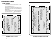
A-4 xi Series Installation Guide RGB 400xi The dashed line indicates the cut-out area (3.95"H x 7.58"W) for installing the electrical wall box. To install the interface without a wall box, use the cut-out area (2.80"H x 7.275"W) indicated by the dotted line. RGB 460xi Dual, RGB 468xi, or RGB 478xi 4-gang Cut-out Template The light gray area represents the layout of the electrical box (3.75"H x 7.38"W) against the rear of the RGB 460xi Dual, RGB 468xi, or RGB 478xi front panel.