RGB 500 AKM RGB 560 AKM Architectural Series Universal Interfaces with Audio and ADSP™ 68-468-02 Printed in the USA
Precautions Safety Instructions • English This symbol is intended to alert the user of important operating and maintenance (servicing) instructions in the literature provided with the equipment. This symbol is intended to alert the user of the presence of uninsulated dangerous voltage within the product's enclosure that may present a risk of electric shock. Warning Power sources • This equipment should be operated only from the power source indicated on the product.
Table of Contents Chapter 1 • Introduction ....................................................................................................... 1-1 About the Interfaces ....................................................................................................... 1-2 Features ................................................................................................................................... 1-2 RGB 500 AKM and RGB 560 AKM features ..................................................
Table of Contents, cont’d ii RGB 500 AKM and RGB 560 AKM Table of Contents
RGB 500 AKM and RGB 560 AKM 1 Chapter One Introduction About the Interfaces Features
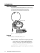
Introduction, cont’d Introduction About the Interfaces Extron’s RGB 500 AKM and RGB 560 AKM interfaces are universal, analog, computer-video interfaces with 300 MHz (-3dB) video bandwidth. The interfaces feature Extron’s ADSP™ (Advanced Digital Sync Processing™) to ensure stable sync signal output, while allowing trouble-free centering control. Up to three interfaces can be installed in an Ackermann floor tank. Ackermann Floor Tank MIN/MA X H.
Serration pulse switch — This DIP switch-selectable feature adds or strips the serration pulses from the signal to make it compatible with digital display devices. Use the serration pulse switch if flagging or bending occurs at the top of the video display. Gain/peaking adjustment — Output gain and peaking levels may be adjusted individually for red, green, and blue channels by using jumpers that are accessible inside the enclosure.
Introduction, cont’d 1-4 RGB 500 AKM and RGB 560 AKM Introduction
RGB 500 AKM and RGB 560 AKM 2 Chapter Two Installation and Operation Front Panel Features Installation Overview Installation and Operation Instructions
Installation and Operation, cont’d Installation and Operation Front Panel Features 3 2 4 5 6 7 AUDIO INPUT H. SHIFT HIGH Z MIN/MAX RGB 500 AKM with ADSP TM 8 1 Figure 2 — RGB 500 AKM front panel 3 2 4 6 7 AUDIO 9 INPUT ID PIN 4 ID PIN 11 H.
5 Video input termination toggle switch (RGB 500 AKM only) — The toggle switch on the front panel allows you to select video input impedance. Set the toggle switch to the top position for high Z when a local monitor is connected, or set it to the bottom position for 75 ohm impedance when no local monitor is connected. 6 DIP switch access cover and DIP switches — Use a screwdriver to remove the cover to gain access to the DIP switches.
Installation and Operation, cont’d 6 — Vertical sync pulse width For some digital display devices, if no picture appears, the picture cuts in and out, or the picture is scrambled, you may need to select the wide vertical sync pulse width. ON — When this switch is set to On, narrow sync pulse width is selected. OFF — When this switch is set to Off, wide sync pulse width is selected. (Default setting.
Installation Overview To install the interface, follow these basic steps: 1 Set the DIP switches, located inside the access panel (see page 2-3), and the gain/peaking adjustment jumpers, located inside the enclosure. (See below.) 2 Set the front panel video termination toggle switch on the RGB 500 AKM, or set the front panel ID bit DIP switches on the RGB 560 AKM. (See page 2-4.) 3 Connect the signal output and power cables. (See “Attaching output cables” on page 2-6.
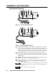
Installation and Operation, cont’d AUDIO INPUT Remove (2) Screws ID PIN 4 ID PIN 11 H. SHIFT MIN/MAX BUFFERED LOCAL OUT RGB 560 AKM with ADSPTM Remove (2) Screws J18 J17 J16 Remove (2) Screws Use Needlenose Pliers to move jumpers Front Face PC Board (Inside) Figure 4 — Setting the gain/peaking jumpers 2. Locate the gain/peaking jumpers on the wider of the two circuit boards attached to the back of the faceplate (figure 4).
Connect the sleeve to ground (GND). Connecting the sleeve to a negative (-) terminal will damage the audio output circuits. Unbalanced Output Tip See Warning Sleeve (GND) Tip See Warning Balanced Output Tip Ring Sleeve (GND) Tip Ring Figure 5 — Wiring for audio output Power connector Attach the 3-pole, 3.5 mm captive screw power connector to a 12 to 24VDC or 12 to 24VAC, .5A (minimum), external power supply, such as Extron’s #70-055-01. The center pole contains no conductor.
Installation and Operation, cont’d 3. If the image appears, but it looks scrambled or cuts in and out, check the DIP switch settings. If all switches are already set to what should be the correct settings for the connected input and output devices, try different settings. If the display device is digital (including LCD, DLP, and plasma devices), try changing the vertical sync pulse width (see page 2-4).
RGB 500 AKM and RGB 560 AKM A Appendix A Specifications
Specifications, cont’d Specifications Video Gain ................................................ Unity (0.70V p-p), (0.725V p-p) 50% peaking, (0.75V p-p) 100% peaking Bandwidth ..................................... 300 MHz (-3dB) Video input Number/signal type ................... 1 analog RGBHV, RGBS, RGsB, RsGsBs Connectors RGB 500 AKM 1 9-pin D male, MBC/LBC cable or buffer RGB 560 AKM 1 15-pin HD female Minimum/maximum levels ....... Analog ....... 0.3V to 1.5V p-p with no offset Impedance ............
Audio input Number/signal type ................... Connectors ................................... Impedance .................................... Maximum level ............................ 1 PC level stereo, unbalanced 1 3.5 mm stereo jack, 2 channel; tip (L), ring (R), sleeve (ground) 10 kohms, DC coupled +8.5dBu, (unbalanced) at stated %THD+N Audio output Number/signal type ................... Connectors ................................... Impedance .................................... Gain error .......
Specifications, cont’d A-4 RGB 500 AKM and RGB 560 AKM Specifications
RGB 500 AKM and RGB 560 AKM B Appendix B Part Numbers Interfaces Cables Other Accessories
Part Numbers, cont’d Part Numbers Interfaces Extron Part Part number RGB 500 AKM 60-313-01 RGB 560 AKM 60-384-01 Cables RGB 500 AKM Laptop breakout cables* LBC VGA HR 6’ Part number 26-244-01 LBC VGA HR 6’ A 26-441-02 LBC Mac HR 6’ 26-363-01 LBC Mac HR 6’ A 26-442-02 LBC Sun HR 6’ (61 kHz) 26-413-01 LBC Sun HR 6’ A (61 kHz) 26-443-02 LBC Sun HR 6’ (71 kHz) 26-413-02 LBC Sun HR 6’ A (71 kHz) 26-444-02 LBC Sun HR 6’ (81 kHz) 26-413-03 LBC Sun HR 6’ A (81 kHz) 26-445-02 *Laptop breako
Adapter laptop breakout cables Part number Mac 15-pin HD F adapter cable kit w/ audio 70-156-01 13W3 15-pin HD F adapter cable kit w/ audio 70-157-01 RGB 500 AKM and RGB 560 AKM High-resolution cables Part number BNC-5-3’HR 26-260-15 BNC-5-6’HR 26-260-01 BNC-5-12’HR 26-260-02 BNC-5-25’HR 26-260-03 BNC-5-50’HR 26-260-04 BNC-5-75’HR 26-260-16 BNC-5-100’HR 26-260-05 BNC-5-3’HRP (plenum) 26-378-01 BNC-5-6’HRP (plenum) 26-378-02 BNC-5-12’HRP (plenum) 26-378-03 BNC-5-25’HRP (plenum) 2
Part Numbers, cont’d B-4 RGB 500 AKM and RGB 560 AKM Part Numbers
Extron’s Warranty Extron Electronics warrants this product against defects in materials and workmanship for a period of two years from the date of purchase.