Installation Guide RJ-45 to RJ-11 Conversion Kit Installation Instructions for HSA 400 Series and HSA 800 Series Enclosures www.extron.com Extron Electronics, USA Extron Electronics, Europe Extron Electronics, Asia Extron Electronics, Japan 1230 South Lewis Street Anaheim, CA 92805 USA 714.491.1500 Fax 714.491.1517 Beeldschermweg 6C 3821 AH Amersfoort The Netherlands +31.33.453.4040 Fax +31.33.453.4050 135 Joo Seng Road, #04-01 PM Industrial Building Singapore 368363 +65.6383.4400 Fax +65.6383.
Precautions Safety Instructions • English This symbol is intended to alert the user of important operating and maintenance (servicing) instructions in the literature provided with the equipment. This symbol is intended to alert the user of the presence of uninsulated dangerous voltage within the product's enclosure that may present a risk of electric shock. Caution Read Instructions • Read and understand all safety and operating instructions before using the equipment.
Table of Contents Chapter 1 • HSA 400, 402 Installation ............................ 1-1 Introduction ............................................................................. 1-2 Removing the HSA from the Table ............................... 1-4 Removing the Front Panel Connector ........................ 1-6 Replacing the Lower Enclosure Connector .............. 1-7 Replacing the Front Panel Connector and Reassembling the HSA ........................................................
Table of Contents, cont’d RJ-45 to RJ-11 Conversion Kit This page intentionally left blank 1 Chapter One HSA 400, 402 Installation Introduction Removing the HSA from the Table Removing the Front Panel Connector Replacing the Lower Enclosure Connector Replacing the Front Panel Connector and Reassembling the HSA Routing the AAP Cables ii RJ-45 to RJ-11 Conversion Kit • Table of Contents
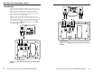
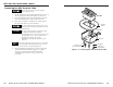
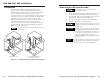
HSA 400, 402, Installation, cont’d Introduction HSA 402 120-240 The Extron HSA 400 and HSA 402 ship with Category (CAT) 6 cables terminated with RJ-45 connectors between the front panel and lower enclosure bezel plug-ins. Some users prefer a telephone (RJ-11) connector. This conversion kit consists of a length of telephone cable terminated with RJ-11 connectors to replace one of the CAT 6/RJ-45 cables. Figure 1-1 shows the location of the bezel plug-ins on the underside and front panel of the HSA 400.
HSA 400, 402, Installation, cont’d Removing the HSA from the Table 125 Ensure that AC power is disconnected before servicing the HSA unit. 1. Disconnect the IEC power cord and the RJ-45 connectors from the underside of the surface mount enclosure. 3. Disconnect any cables connected to the existing AAPs at the ends of the cables away from the HSA. HS A 40 2 4. 1-4 On the underside of the table, remove the two bolts that secure the clamshell to the HSA (figure 1-3).
HSA 400, 402, Installation, cont’d Removing the Front Panel Connector 1 Through the access hole in the rear of the enclosure, cut the tie wraps that bundle the power and CAT 6 cables. 2. Through the access hole in the rear of the enclosure, disconnect the 3-prong cable connector on the interior AC cable (figure 1-4). 4. With a tweeker, push down on and gently twist on the front of each RJ-45 connector detent to disconnect the connector from the rear of the front panel bezel plug-in. 5.
HSA 400, 402, Installation, cont’d 2. Note how the disconnected CAT 6 cable is routed inside the HSA and then gently pull the cable free. 3. Route the conversion kit telephone cable in the same fashion as the removed CAT 6 cable. 4. Replacing the Front Panel Connector and Reassembling the HSA 1. Reach your hand through the access hole in the rear of the enclosure and snap the replacement RJ-11 connector onto the interior of the lower enclosure bezel plug-in.
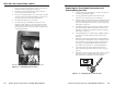
HSA 400, 402, Installation, cont’d Routing the AAP Cables 1. Open the top panel to extend the AAP cables to their maximum pull. 2. Experiment with AAP cable positioning to ensure that the cables do not rub against the edges of the AAP cable hole and to ensure that the cable pull does not restrict the movement of the top panel. Figure 1-9 shows the cables routed to the side, which proved effective in tests at Extron. 3.
HSA 800, 802, 822 Installation Introduction Removing the HSA from the Table The Extron HSA 800, HSA 802, and HSA 822 ship with Category (CAT) 6 cables terminated with RJ-45 connectors between the front panel(s) and lower enclosure bezel plug-ins. Some users prefer a telephone (RJ-11) connector. This conversion kit consists of a length of telephone cable terminated with RJ-11 connectors to replace one of the CAT 6/RJ-45 cables.
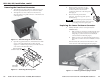
HSA 800, 802, 822 Installation, cont’d 4. On the underside of the table, remove the two bolts that secure the clamshell to the surface mount enclosure (figure 2-2). Lift the enclosure out of the table. Ensure that the cables connected to the AAPs do not snag or pull on any protrusions. 5. Figure 2-2 shows an HSA 802. For the purposes of this procedure, the HSA 800 and HSA 822 are physically similar. On all AAP panels, remove the four screws on the right and left sides of the AAP panel (figure 2-3).
HSA 800, 802, 822 Installation, cont’d 4. Inside the bottom frame, identify the RJ-45 connector to be replaced. With a tweeker, push down on and gently twist on the front of the RJ-45 connector detent to disconnect the connector from the bottom frame bezel plug-in. 3. Open and close the top panel while you experiment with the routing of the cable bundle. Find a routing that allows the top panel to open and close smoothly.
HSA 800, 802, 822 Installation, cont’d Routing the AAP Cables 1. Open the top panel to extend the AAP cables to their maximum pull. 2. Experiment with AAP cable positioning to ensure that the cables do not rub against the edges of the AAP cable hole and to ensure that the cable pull does not restrict the movement of the top panel. Figure 2-6 shows the cables routed to the side, which proved effective in tests at Extron. Figure 2-6 shows an HSA 822.