User’s Manual SCS 300 Sync Converter/Stabilizer 68-1251-01 Rev.
Precautions Safety Instructions • English This symbol is intended to alert the user of important operating and maintenance (servicing) instructions in the literature provided with the equipment. This symbol is intended to alert the user of the presence of uninsulated dangerous voltage within the product’s enclosure that may present a risk of electric shock. Caution Read Instructions • Read and understand all safety and operating instructions before using the equipment.
Precautions 安全须知 • 中文 这个符号提示用户该设备用户手册中 有重要的操作和维护说明。 这个符号警告用户该设备机壳内有 露的危险电压,有触电危险。 注意 阅读说明书 • 用户使用该设备前必须阅读并理解所有 安全和使用说明。 保存说明书 • 用户应保存安全说明书以备将来使用。 遵守警告 • 用户应遵守产品和用户指南上的所有安全 和操作说明。 避免追加 • 不要使用该产品厂商没有推荐的工具或追 加设备,以避免危险。 警告 电源 • 该设备只能使用产品上标明的电源。 设备必须 使用有地线的供电系统供电。 第三条线(地线)是 安全设施,不能不用或跳过 。 拔掉电源 • 为安全地从设备拔掉电源,请拔掉所有设 备后或桌面电源的电源线,或任何接到市电系统的 电源线。 电源线保护 • 妥善布线, 避免被踩踏,或重物挤压。 维护 • 所有维修必须由认证的维修人员进行。 设备内 部没有用户可以更换的零件。为避免出现触电危险 不要自己试图打开设备盖子维修该设备。 通风孔 • 有些设备机壳上有通风槽或孔,它们是用来 防止机内敏感元件过热。 不要用任何东西挡住通 风孔。 锂电池 • 不正确的更换电池会有爆炸的危险。
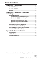
Table of Contents Chapter One • Introduction ................................................... 1-1 About this Manual ..................................................................... 1-2 About the SCS 300 ..................................................................... 1-2 Features ......................................................................................... 1-2 Chapter Two • Installation, Connection, and Settings ....................................................................
Table of Contents cont'd This page was deliberately left blank.
SCS 300 Sync Converter/Stabilizer 1 Chapter One Introduction About this Manual About the SCS 300 Features
Introduction About this Manual This manual documents the features, installation, operation, and specifications of the Extron SCS 300 Sync Converter/ Stabilizer. About the SCS 300 The SCS 300 Sync Converter/ Stabilizer is a 1U high, quarter rack width, 6" deep, sync converter and stabilizer with Advanced Digital Sync Processing (ADSP™).
SCS 300 Sync Converter/Stabilizer 2 Chapter Two Installation, Connection, and Settings Mounting the SCS 300 Rear Panel Features and Connection Front Panel Features and Settings Auto Memory for H-shift Control Settings Front Panel DIP Switch Settings
Installation, Connection, and Settings Mounting�������������� the SCS 300 The SCS 300 can be mounted on a 1U rack shelf, under or through a desk, or attached to the projector pole. UL requirements for rack mou�������������� nted devices The following Underwriters Laboratories (UL) requirements pertain to the safe installation of the SCS 300 in a rack. 1.
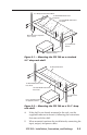
9.5" Deep Universal Rack Shelf 1/2 Rack Width Front False Faceplate 1/4 Rack Width Front False Faceplate Both front false faceplates use 2 screws. (2) 4-40 x 3/16" Screws Use 2 mounting holes on opposite corners. Figure 2-1 — Mounting the SCS 300 on a standard 9.5" deep rack shelf 6" Deep Rack Shelf 1/2 Rack Width False Front Face Plate 1/4 Rack Width False Front Face Plate (2) 4-40 x 3/16" Screws Use 2 mounting holes on opposite corners. Figure 2-2 — Mounting the SCS 300 on a 1U 6" deep rack shelf 4.
Installation, Connection, and Settings, cont’d Mounting the SCS 300 under a d���� esk To mount the SCS 300 under a desk or in a podium using the under desk mounting kit (Extron part # 70-077-01, MBU 125), do the following: 1. Attach the mounting brackets to the SCS 300 using the four machine screws supplied with the mounting kit as shown in figure 2-3. Figure 2-3 — Attaching the under desk brackets 2-4 2.
Mounting the SCS 300 through a ����� desk To mount the SCS 300 through a desk or table using the through desk mounting kit (Extron part # 70-077-02, MBD 129), do the following: 1. Attach the mounting brackets to the SCS 300 using four machine screws and washers supplied with the mounting kit, as shown in figure 2-4. Figure 2-4 — Attaching the through desk brackets 2. Holding the device up against the underside of the surface to which you are mounting, mark the four screw holes. 3.
Installation, Connection, and Settings, cont’d Mounting the SCS 300 to a projector pole To mount the SCS 300 to a projector pole, use one of the optional accessory Projector Mounting Kits (PMK series). To install the Extron PMK, follow the instructions supplied with the kit. To attach the SCS 300 to the PMK, use the two supplied 4-40 x 3/16" screws in the opposite diagonal corners of the device base to secure it to the bracket, as shown in figure 2-5.
Rear Panel Features and Connection The rear panel has three main features:. 2 INPUT POWER R G B H/HV V 12V 0.4A MAX OUTPUT SCS 300 3 1 ` Figure 2-7 — Rear Panel features a Power connection point — This dedicated female, 3.5mm, 2-pole captive screw connector enables connection of the 12 VDC external power supply. Wire the power supply cord into the supplied male orange connector as shown in figure 2-8. POWER 12V 0.4A MAX C Power supply voltage polarity is critical.
Installation, Connection, and Settings, cont’d Insert the wired connector into the female, 2-pole captive screw connector (a) marked "power". C b When using a compatible power source from the projector, verify that it is 12 VDC positive. Input connectors — Non-interlaced video signal input is made on these five female BNC connectors, labeled Input. Connect the input devices' video signal cables to the BNC connectors, ensuring the correct cable matches the labeled input connector.
Front Panel Features a������������ nd Settings The front panel has four features: 2 4 3 H-SHIFT INPUT SYNC 10K FORCE NEG SYNC COMP SYNC OUT SOG OUT RsGsBs OUT SERR REMOVAL NO SYNC PROC SPARE 1 ON OFF OUTPUT ON 1 2 3 4 5 6 7 8 SCS 300 SYNC CONVERTER/STABILIZER WITH ADSP Figure 2-9 — Front Panel features b c d Power LED — This green LED is lit when the device has power. H-SHIFT Horizontal shift control — This recessed rotary dial adjusts the horizontal shift.
Installation, Connection, and Settings, cont’d Front Panel DIP Switch S�������� ettings INPUT SYNC 10K FORCE NEG SYNC COMP SYNC OUT SOG OUT RsGsBs OUT SERR REMOVAL NO SYNC PROC SPARE The bank of eight DIP switches allows the user to control sync input termination, sync polarity, output sync format, and serration pulses, or to disable all sync processing. Switches furthest to the right takes the highest priority.
SCS 300 Sync Converter/Stabilizer A Appendix A Reference Material Specifications Included Parts Optional Accessories
Reference Material Specifications Video Gain ................................................. Unity Bandwidth . .................................... 300 MHz @ -3 dB Video input Number/signal type...................... 1 analog RGBHV, RGBS, RGsB, RsGsBs N Not compatible with interlaced signals. Connectors ..................................... Nominal level................................. Minimum/maximum levels......... Impedance . .................................... Horizontal frequency...............
Max. propagation delay................ 48 nS Max. rise/fall time......................... 3.5 nS Polarity RGBHV,................................ For RGBHV input, output is positive or negative (follows input) or is forced negative (switch selectable). RGBS, RGsB, RsGsBs......... Negative General Power .............................................. 100 VAC to 240 VAC, 50/60 Hz, external, auto-switchable; to 12 VDC, 1 A, regulated Power input requirement.............. 12 VDC, 0.4 A Temperature/humidity......
Reference Material, cont'd Included Parts Included parts SCS 300 Replacement part number 60-811-01 Rubber feet (4) 12 VDC Desktop power supply (1) IEC cord (1) 2-pole, captive screw plug, orange (1) 10-762-01LF Tweeker (small screwdriver) SCS 300 User’s manual Optional Accessories These items can be ordered separately. Item A-4 Part number PMK 350, black, white 70-563-02, 03 PMK 250 black, white 70-526-02, 03 PMK 200 70-077-04 RSU 129, 9.5" deep Universal rack shelf 60-190-01 RSB 129, 9.
This page was deliberately left blank.
FCC Class A Notice Note: This equipment has been tested and found to comply with the limits for a Class A digital device, pursuant to part 15 of the FCC Rules. These limits are designed to provide reasonable protection against harmful interference when the equipment is operated in a commercial environment. This equipment generates, uses and can radiate radio frequency energy and, if not installed and used in accordance with the instruction manual, may cause harmful interference to radio communications.
www.extron.com Extron Electronics, USA 1230 South Lewis Street Anaheim, CA 92805 800.633.9876 714.491.1500 FAX 714.491.1517 Extron Electronics, Europe Beeldschermweg 6C 3821 AH Amersfoort, The Netherlands +800.3987.6673 +31.33.453.4040 FAX +31.33.453.4050 Extron Electronics, Asia 135 Joo Seng Rd. #04-01 PM Industrial Bldg., Singapore 368363 +800.7339.8766 +65.6383.4400 FAX +65.6383.4664 © 2007 Extron Electronics. All rights reserved.