User’s Manual IPL T SF24 and SFI244 Series www.extron.com Extron Electronics, USA Extron Electronics, Europe Extron Electronics, Asia Extron Electronics, Japan 1230 South Lewis Street Anaheim, CA 92805 USA 714.491.1500 Fax 714.491.1517 Beeldschermweg 6C 3821 AH Amersfoort The Netherlands +31.33.453.4040 Fax +31.33.453.4050 135 Joo Seng Road, #04-01 PM Industrial Building Singapore 368363 +65.6383.4400 Fax +65.6383.4664 Daisan DMJ Building 6F 3-9-1 Kudan Minami Chiyoda-ku, Tokyo 102-0074 Japan +81.
Precautions Safety Instructions • English This symbol is intended to alert the user of important operating and maintenance (servicing) instructions in the literature provided with the equipment. This symbol is intended to alert the user of the presence of uninsulated dangerous voltage within the product's enclosure that may present a risk of electric shock. Caution Read Instructions • Read and understand all safety and operating instructions before using the equipment.
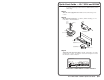
Quick Start Guide — IPL T SF24 and SFI244 To install and set up an IPL T SF24 or SFI244 interface, follow these steps: Step 1 Turn all of the equipment off and disconnect it from the power source. Step 2 Mount the IPL T interface, on a device, under a desktop, or on a rack shelf, as illustrated below.
Quick Start Guide — IPL T SF24, IPL T SFI244, cont’d Table of Contents Chapter 1 • Introduction .......................................................... 1-1 Step 4 Attach the serial communication cables from the IPL T unit to the devices being controlled. Step 5 Connect power cords and turn on the equipment in the following order: output devices (projectors, monitors, speakers), the IPL T interface, the serial controller or computer (PC), then all input devices (DSS, cable boxes, etc.).
Table of Contents, cont’d Communication with the Interface .............................. 4-6 Web server ............................................................................. 4-6 Accessing and using the Web server ................................... 4-6 Establishing or changing system or port settings ............... 4-7 Controlling IR devices or sending IR commands (SFI244 only) ...............................................................................................
IPL T SF24 and SFI244 1 Chapter One Introduction About this Manual About the IPL T SF24 and SFI244 Interfaces Features
Introduction About this Manual This manual contains information about the Extron IPL T SF24 (Extron part #60-544-02) and the IPL T SFI244 (Extron part #60-544-06) Ethernet control interfaces. It includes information on how to install, configure, and operate each system. When information in this manual applies to both models, they may be referred to generally as an IPL T unit or interface.
Introduction, cont’d Easily configured and controlled — • Using a standard Web browser (Internet Explorer V5.5, Netscape V6.0 or higher) and Web-based interface. • Using a standard Telnet client application. • Requires no centralized processor to operate within a system. Choice of mounting options — Can be mounted under a desktop or podium, on a projector mount, or on a rack shelf.
Installation and Operation Installation Overview To install and set up the IPL T SF24 and SFI244 interfaces, follow these steps: 1 Turn all of the equipment off. Make sure that the video sources (DSS, cable boxes, or other devices), the IPL interface, the output devices (monitors, VCRs, projectors, etc.) and the serial controller are all turned off and disconnected from the power source. 2 Mount the IPL T unit. See Mounting the IPL T interface below. 3 Attach the cables.
Installation and Operation, cont’d Furniture or projector mounting In addition to using the IPL T unit on a rack, it can also be furniture or projector mounted. Furniture mount or projector mount the interface using the optional mounting kit (Extron part #70-212-01, furniture, or Extron part #70-217-01, projector) as follows: 1. Attach the mounting brackets to the interface with the machine screws provided (figure 2-3). 2. If feet were previously installed on the bottom of the interface, remove them. 3.
Installation and Operation, cont’d Serial communication A A 3 Flex I/O ports — Four I/O ports permit connection of switches and sensors to provide input to the system, and contact closure activation of relays for power, screen, or projector lift control (output). Plug a serial cable into this 3.5 mm, 5-pole captive screw connector for flexible I/O connection. 4 COM ports — Plug a 3.5 mm, 5-pole captive screw connector into this socket for serial ports 1 and 2.
Installation and Operation, cont’d Identification 7 UID # — The unique User ID Number (MAC address) of the unit (for example, 00-05-A6-00-00-01). Motion Detector Information flows both ways through the IPL T SF24 and SFI244 interfaces, but control only goes from the LAN connection to the serial ports. See figure 2-10. Information 00-05-A6-xx-xx-xx RS-232 POWER FLEX I/O LAN 12V .
Installation and Operation, cont’d 1 On/Off indicator LED — A green LED lights to indicate that the interface is receiving power. 2 Reset button (recessed) — See Resetting the unit later in this chapter for details on this multiple function Reset button. 3 IR pickup sensor — Receives infrared signals from the MLA remote.
Installation and Operation, cont’d • If the events are currently stopped following the momentary (<1 second) press, the Power LED will flash twice indicating the starting of events. IPL T SF24 and SFI244 or • If events are currently running following the momentary (<1 second) press, the Power LED will flash three times indicating the stopping of events. Each flash will last for .25 seconds. Nothing happens if the momentary press does not occur within 1 second.
Connection and Configuration, cont’d Serial connection Connecting the Hardware To connect the IPL T interface, connect the input and output devices to the unit using figure 3-1 as a guide. Please note, prior to connecting the IPL T unit to a local area network (LAN) you must initially connect a PC directly to the IPL unit and change the default IP address to an address specified by your network administrator (for a LAN connection).
Connection and Configuration, cont’d Place the head of each IR emitter over or directly adjacent to the controlled device’s IR receiver. 2. 00-05-A6-00-04-15 POWER FLEX I/O LAN 12V .5A MAX COM1 TX RX COM2 1 2 3 4 IR 1 2 3 4 S G S G S G S G TX RX IPL T SFI244 2-pole captive screw connectors can also be used. 100' A 100' run can be used with a maximum of 4000' for multiple IR emitters.
Connection and Configuration, cont’d In order to use this setup method, both your computer and IPL T interface must be connected to the same LAN. Or, you may use a crossover Ethernet cable to connect the device server directly to your computer’s Ethernet card. After issuing this command, the unit will change to the new address and start responding to the ping requests, as shown below.
Connection and Configuration, cont’d 4. Select Internet Protocol (TCP/IP) from the list and click on Properties. (If you are using Windows 2000, right click Local Area Connection and select Properties from the menu, then select Internet Protocol (TCP/IP) from the list and click on Properties again.) If Internet Protocol (TCP/IP) is not on the list, it must be added (installed). Refer to your Windows user’s manual or the online Help system for information on how to install the TCP/IP protocol. 5.
Communication and Control, cont’d Digital input Ports Overview Flex I/O ports Extron Flex I/O ports are configurable input or output ports designed to provide connectivity to various devices such as motion detectors, alarms, lights, LEDs, buttons, photo (light) sensors, temperature sensors, relays, etc.
Communication and Control, cont’d If the integrator selects threshold voltages that are more than 0.1V apart, a deadband, or hysteresis, will be established. In the example below, the lower threshold voltage is set at +6VDC and the upper threshold is set at +16VDC. The colored bands show state changes on the logical outputs. The range between 6-16VDC is the deadband in which the signal can fluctuate without affecting the input state.
Communication and Control, cont’d will not happen the first time you access the interface, as no password is set at the factory). Pacing and handshaking are not supported on captive screw connectors. All of the bidirectional serial ports are completely software configurable. Baud rates can be set up to 115Kbs. Using the Simple Instruction Set (SIS) commands found in the Command/ Response Table for Simple Instruction Set later in this chapter, these ports can be configured to control most serial devices.
Communication and Control, cont’d Controlling IR devices or sending IR commands (SFI244 only) In order to send IR commands to IR devices via the default Web pages, do the following: 1. Select the File Management tab and the File Management screen (figure 4-17) is displayed. 2. Upload the IR driver to the box by clicking the browse button and locating the appropriate driver. The IR driver file must be named numerically (ranging from 0 to 99). File names must end with an .eir extension. (e.g., 0.eir, 24.
Communication and Control, cont’d To clear a password, enter a single space, repeat the entry, and press ‘Submit’. If there is no administrator password, your user password will not be saved. Editing and adding e-mail alerts If you have created scheduled events or monitoring tasks on the IPL T interface, you can write an e-mail alert with a message corresponding to that event or task (e.g., a timer notification indicating it’s time to replace a projector light bulb).
Communication and Control, cont’d c. Click Save to keep changes to recipient e-mail addresses and file names. CAUTION To upgrade the firmware: 1. File names must end with an .eml extension. Due to the 7 character limit for full file names, it’s advised that you use numeric titles (e.g., 1.eml, 24.eml). Numeric titles reduce the characters of the file name, and assist in keeping the alert files organized. However, alphabetical titles are permitted.
Communication and Control, cont’d 2. Click the Browse button to locate the file you want to upload. 3. Click the Upload File button to upload the file. The file will be added to the list of files under the Files column. After ten files have been loaded, additional file management pages will appear in the page navigation area (on the right side of the screen). To delete unwanted files: 1. Select the File Management tab and the File Management screen (figure 4-17) is displayed. 2.
Communication and Control, cont’d where xx equals the two character representation of the hex byte that needs to be sent (e.g., a comma would be represented as %2C). At this point the driver is populated with unlearned functions. To learn driver functions: 1. 2. Select those functions that are to be learned (see figure 4-20). Then begin a learning session by pressing the learn toolbar button.
Communication and Control, cont’d Symbol definitions = CR/LF (carriage return/line feed) X18 = Hardware (MAC) address (xx-xx-xx-xx-xx-xx). X19 = Subnet mask (xxx.xxx.xxx.xxx); leading zeros in each of four fields are optional in setting values, and are suppressed in returned values.
Communication and Control, cont’d X38 = Event data size: b = bit; B = byte (8 bit); S = short (16 bit); L = long (32 bit) X56 This parameter is case sensitive. X39 = Event data to write. X40 = I/O mode: 0 = input; 1 = output; 2 = input plus pull-up resistor; 3 = output plus pull-up resistor; 4 = analog in; 5 = analog in w/ pull-up; 6 = adjust in (requires X55 & X56 thresholds); 7 = adjust in w/pull-up (requires X55 & X56 thresholds). X55 & X56 thresholds are not required for modes 0-5.
IPL T SF24 and IPL T SFI244 • Communication and Control ASCII (Telnet) URL Encoded (Web) Response W X1 %2A X17 %2A X20 %2A X21 RS| X2 W X1 %2A X25 %2C X26 %2C X27 %2C X28 CP| W X1 CP| W X1 %2A X30 %2C X31 CF| W X1 CF| W X1 %2A X17 %2A X20 %2A X23 CE| W X1 CE| W X1 %2A X50 %2A X53 CD| W X1 CD| W X1 %2A0CD| response from command Cpn X1 •Ccp X25 , X26 , X27 , X28 X25 , X26 , X27 , X28 Cpn X1 •Cfl X30 , X31 X30 , X31 Cpn X1 •Cce X17 , X20 , X23 X17 , X20 , X23 Cpn X1 •Ccd X50 , X53 X50 , X53 Cpn X1 •Ccd 0,
ASCII (Telnet) URL Encoded (Web) Response IR/Serial Data port (SFI244 only) IPL T SF24 and IPL T SFI244 • Communication and Control Send IR command 28 Esc X1 {file #}, {function#}, X59 IR Get IR command info 28 Esc {file#}, {function#}, IR Irs X1 , {file#}, {function#}, X57 {description text} Firmware Version/Part Number/Information Query firmware version Query verbose version information Query firmware version Query bootstrap version Query factory firmware version Query updated firmware version
ASCII (Telnet) IPL T SF24 and IPL T SFI244 • Communication and Control URL Encoded (Web) Response W%20CU| Ipu• IP Setup Commands, continued Clear user password24 Esc •CU 24 Read user password Esc CU WCU| X33 Set verbose mode Read verbose mode Read connection’s security level Esc X5 CV Esc CV Esc CK W X5 CV| WCV| W CK| Vrb X5 X5 X52 Configure broadcast mode Esc X64 EB W X64 EB| Bmd X64 View broadcast mode Get connection listing Esc EB Esc CC W EB| W CC| X64 File Commands Get listing
Communication and Control, cont’d X6 Nvr X6 (responds when done) Zpf Zpx Zpq Del•filename Evt X39 Ego Est Enm# In the IPL T interface family, varying degrees of customization are possible. Server side includes make it possible to obtain information from the unit and display the information on Web pages. URL encoding allows you to send information and commands to the unit to change its configuration or provide you with feedback.
Communication and Control, cont’d URL with a Query String using a Remote SIS command Server Side Include Using a Remote SIS command SIS Command SIS Command