
User`s manual


IPL T SF24 and IPL T SFI244 • Installation and Operation
IPL T SF24 and IPL T SFI244 • Installation and Operation
Installation and Operation, cont’d
If the Reset button is continuously held down, every 3
seconds the LED will pulse (blink) and put the unit in a
different mode, corresponding to the underscored notes
in Modes 3 through 5. The Mode 5 LED blinks three
times, the third blink indicating that it’s the last mode.
The following modes are listed as separate functions, not
as a continuation from Mode 1 to Mode 5.
Mode 1 — Holding the Reset button while applying power will
default the unit back to the base firmware that shipped
with the unit from the factory. Event scripting will not
start when the unit is powered on in this mode. This
allows you to recover a unit that has incorrect code or
updated firmware running. All user files and settings are
maintained. User Web pages may not work correctly if
using an earlier firmware version.
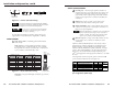
Mode 2 — Momentarily (<1 second) pressing the Reset button
and typing three “+’s” into any available COM port on the
IPL unit (e.g., “+++” within 2 seconds of the momentary
press) will enable the connected COM port to be used as a
console port to send SIS commands. If the three “+’s” are
not entered in the 2 second time frame, the COM port will
remain or return to being a control port only.
There will be no LED indication. If the three “+’s” are
entered within the 2 second time frame, the copyright
message below will be shown.
This will indicate that you have successfully enabled the
COM port.
Mode 3 — Holding the Reset button until the Power LED
blinks once (3 seconds) followed by a momentary
(<1 second) press will turn events either on or off,
depending on the current state of the events:
2-11
2-10
1
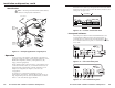
On/Off indicator LED — A green LED lights to indicate
that the interface is receiving power.
2
Reset button (recessed) — See Resetting the unit later in this
chapter for details on this multiple function Reset button.
3
IR pickup sensor — Receives infrared signals from the
MLA remote.
4
COM ports — A green LED indicates that data is being
transmitted or received (TX or RX); ready to send or ready
to accept data (RTS or CTS for IPL T SF24) from the
corresponding serial port (1 and 2).
5
I/O ports — A green LED indicates that the corresponding
I/O port (1-4) is active.
6
IR/Serial ports — A green LED lights to indicate that the
corresponding serial port (1-4) is transmitting data.
7
100 LED — A green LED lights to indicate that the
connection speed is 100 Mbs. If the LED is not lit, the
connection speed is 10 Mbs.
8
Link LED — A green LED indicates that the unit is
connected to an active network.
9
Act (Activity) LED — A yellow LED lights to indicate that
data is being sent/received.
Resetting the unit
There are five reset modes available by using the Reset button
(
2
) on the front panel. The Reset button is recessed, so use of a
pointed stylus, ballpoint pen, or Extron Tweeker is suggested.
CAUTION
Review the reset modes carefully. Use of the wrong
reset mode may result in unintended loss of flash
memory programming, the reassignment of ports,
or a unit reboot.
CAUTION
The reset modes listed below (with the exception of
Mode 2) will close all open IP and Telnet
connections and close all sockets.