SGS 408 Eight Input, High Resolution, Seamless Graphic Switcher 68-520-01 Rev.
Precautions Safety Instructions • English This symbol is intended to alert the user of important operating and maintenance (servicing) instructions in the literature provided with the equipment. This symbol is intended to alert the user of the presence of uninsulated dangerous voltage within the product's enclosure that may present a risk of electric shock. Warning Power sources • This equipment should be operated only from the power source indicated on the product.
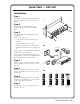
Quick Start — SGS 408 Installation Step 1 Install the four rubber feet on the bottom of the SGS 408 switcher, or mount the switcher in a rack (1). 1 Step 2 Turn off power to the input and output devices, and remove the power cords from them.
Quick Start — SGS 408, cont’d Adjusting an Image From the default screen, press the indicated button. To adjust the preview image, press the button again. Button Right adjustment knob Left adjustment knob Center Size Filter Level Move image horizontally Adjust image width Select horizontal filter Adjust image brightness Move image vertically Adjust image height Select vertical filter Adjust image contrast Configuring the Switcher From the default screen, press the Menu button.
Table of Contents Chapter 1 • Introduction ...................................................................................................... 1-1 About the SGS 408 ............................................................................................................ 1-2 Features ................................................................................................................................... 1-2 Chapter 2 • Installation ............................................................
Table of Contents, cont’d Implementing an established effect ........................................................................... 3-22 Implementing a title ................................................................................................... 3-23 Using executive mode .................................................................................................... 3-23 Optimizing the Image ..............................................................................................
SGS 408 Switcher 1 Chapter One Introduction About the SGS 408 Features
Introduction, cont’d Introduction About the SGS 408 The Extron SGS 408 is an eight-input, high resolution, component video and RGB video matrix switcher. It provides seamless cuts, dissolves, wipes, and titles, as well as scaling capabilities, to bring professionalism and style to live multimedia events and presentations.
• 1360 x 765 (plasma) at 60 Hz, and lock* • 1365 x 1024 (plasma) at 60 Hz, and lock* • 1400 x 1050 (SXGA+) at 50 Hz, 60 Hz, and lock* • 576p (Progressive PAL) at 50 Hz, and lock* • 720p (HDTV) at 50 Hz, 60 Hz, and lock* • 1080p (HDTV) at 50 Hz, 60 Hz, and lock* • 1080i (HDTV) at 50 Hz, 60 Hz, and lock* * See Accu-RATE Frame LockTM below. • Power supply — Includes an internal, 100–240 VAC, 50/60 Hz, autoswitchable power supply.
Introduction, cont’d 1-4 SGS 408 Switcher • Introduction
SGS 408 Switcher 2 Chapter Two Installation Rear Panel Connectors Installation Cable Pinouts
Installation, cont’d Installation Rear Panel Connectors Front panel features are shown on page 3-2. 1 2 3 4 INPUTS 5 6 7 OUTPUTS PREVIEW PROGRAM 8 PROGRAM R/R-Y R/R-Y R/R-Y R/R-Y R/R-Y R/R-Y R/R-Y R/R-Y 7 R R PREVIEW G/Y G/Y G/Y G/Y G/Y G/Y G/Y G/Y G G B/B-Y B/B-Y B/B-Y B/B-Y B/B-Y B/B-Y B/B-Y B/B-Y B B H/HV H/HV H/HV H/HV H/HV H/HV H/HV H/HV H/HV H/HV V V V V V V V V V V PROGRAM DVI OUT REMOTE 100- 240 50/60 Hz 1.2A MAX.
4 If desired, attach a computer or other control device to the RS-232 connector. 5 If desired, attach an RCP 1000 remote control panel. See “Attaching an RCP 1000” on page 2-6. 6 If desired, attach an ECP 1000 event control panel. See “Attaching an ECP 1000” on page 2-6. 7 Plug the switcher, input devices, and output devices into a grounded AC source. 8 Turn on the input and output devices. 9 Use the LCD menu screens to configure the switcher. See “Configuring the SGS 408” on page 3-4.
Installation, cont’d Tabletop/desktop mounting For tabletop or desktop placement, install the self-adhesive rubber feet/pads (provided) onto the four corners of the bottom of the enclosure. Cabling Up to eight input devices that produce component video, RGsB, RGBS, or RGBHV signals, can be connected to the switcher.
Up to 8 Inputs RGB 109xi DVD Player PC Computer Projector CT ION EFFENSIT TRA T INPU NS SITIOTAKE TRAN CUT UT OUTP 8 408 SGSCHER M SWIT GRA PRO IEW PREV PHIC GRA LESS SEAM RATE CTS 2 EFFE 7 1 6 5 M GRA 4 PRO 4 3 3 2 8 1 7 K BLAC 6 ZE FREE 5 VIEW4 PRE ION ICAT MUN COM RCP Tx Rx 3 2 1 K BLAC Program Monitor Preview Monitor SGS 408 ZE FREE Figure 2-5 — Typical SGS 408 application Genlocking Video Inputs for Accu-RATE Frame Lock™ All video inputs to the SGS 408 should be genlocke
Installation, cont’d Attaching an RCP 1000 To attach an RCP 1000 remote control panel to an SGS 408 switcher, plug one end of the RCP comm cable (provided with the RCP 1000) into the 4-pin male XLR connector (labeled “To SGS”) on the back of the RCP 1000, and plug the other end of the cable into the 4-pin female XLR connector (labeled “RCP”) on the back of the SGS 408. Figure 2-7 shows a typical SGS 408/RCP 1000 application.
Projectors SGS 408 CT N EFFE SITIO TRAN INPUT NS SITIOTAKE TRAN CUT UT OUTP 8 HIC GRAP SWIT NS SITIOTAKE TRAN CUT LESS SEAM RATE 1 6 HIC GRAP SWIT NS SITIOTAKE TRAN CUT LESS SEAM RATE 1 6 8 1 7 6 5 IEW4 PREV K BLAC 7 5 6 ZE FREE 5 RCP Tx IEW4 PREV Rx K BLAC ION ICAT MUN COM 6 ZE FREE RCP Tx IEW4 PREV Rx 3 3 2 1 1 K BLAC K BLAC ZE FREE Preview Monitor ION ICAT MUN COM RCP Tx Rx 3 2 2 1 K BLAC ZE FREE SWIT 4 3 3 2 8 1 ZE FREE 408 SGSCHER HIC GRAP 1
Installation, cont’d Making an RCP comm cable Use the following guidelines to make an RCP cable: • At one end, attach a female 4-pin XLR connector. • At the other end, attach a male 4-pin XLR connector. • Connect pins straight through. • Use at least 18 gauge wire paired with 20 gauge wire for power (pin 1), 18 gauge wire paired with 20 gauge wire for ground (pin 4), and 20 gauge twisted-pair wire for communications (attach one pair to pin 3 and the other pair to pin 4).
SGS 408 Switcher 3 Chapter Three Operation Front Panel Controls Default Screen Configuring the SGS 408 Using the Image Controls Selecting an Input Optimizing the Image
Operation, cont’d Operation Front Panel Controls Rear panel features are shown on page 2-2.
3 RCP communication LEDs — Light to indicate that the SGS 408 is communicating with an optional RCP 1000 remote control panel. When the SGS 408 is transmitting data to the RCP 1000, the Tx LED is lit. When the SGS 408 is receiving data from the RCP 1000, the Rx LED is lit. 4 Transition buttons — Control the type of switch that will occur between the program and preview outputs. Cut button — Initiates an immediate seamless switch between the program and preview images.
Operation, cont’d 5 Controls — Display the available controls. The configuration options are available by pressing the Menu button. See “Configuring the SGS 408” below. 6 Current duration — Displays the currently selected effect’s duration. 7 Current effect — Displays the effect and transition that are specified for the active input. See “Applying other effects” on page 3-16 for details. Configuring the SGS 408 To access all the configuration options, you must first enter the LCD menu system.
Selecting the input configuration To select the input configuration, do the following: 1. Press the Menu button. 2. Press the Input Config button (figure 3-6). Input Config Next 1280 x 1024 60 Hz Out Te s t Sync Pattern Out Rate Figure 3-6 — Selecting the input configuration menu 3. Using the right adjustment knob, select the input (figure 3-7). Both the program and preview outputs will display the selected input for adjustments. 4.
Operation, cont’d 6. Depending on the input type, color matrix, Beta-cam control, and Luma/ Setup control can be set by pressing the button below each control (figure 3-7). Color matrix control may be set to either the ITU 601 or ITU 709 standard, Beta-cam control may be set on or off, and Luma/Setup control may be set to either .700V or .714V, on or off. There are four preset component video types available for selection. The settings for each control can be changed by pressing the button below it.
Next Input Config H Pos Out Sync Out Rate RGBHV V Neg Te s t Pattern Figure 3-10 — Selecting the output sync format 3. To select the output sync format, turn the right adjustment knob. The following formats are available: RGBS RGBHV 4. If RGBHV is selected, you can select the polarity. (Otherwise, both horizontal polarity and vertical polarity are negative.) To select the polarity, turn the left adjustment knob. The following options are available: Horizontal Horizontal Horizontal Horizontal 5.
Operation, cont’d 4. To select the test pattern you want to display, turn the left adjustment knob. Figure 3-12 shows the image displayed by each test pattern. Color bars — Used in troubleshooting any RGB problems. Cross hatch — Used in converging displays. Grayscale — Used in setting color balance. This pattern is especially helpful in matching all the screens in a multiple-screen event. Crop — Used in ensuring that the images on all displays fill the screen, are centered, and are the same size.
5. Pressing the leftmost ECP control button toggles between Window and Key (figure 3-15). This determines the function of the Title button on the ECP 1000. ECP Window will display the Program input in the foreground and the smaller Preview title box “cutout” in the background. ECP Key will overlap user defined Preview titlebox text over the Program input. H Shift 0606 V Shift 0341 ECP Window Center Size Reset Ta k e Figure 3-15 — ECP control 6.
Operation, cont’d 8. To return the title its original location and size, press the Reset button (figure 3-18). H Size 0315 V Size 0245 ECP Window Center Size Reset Ta k e Figure 3-18 — Resetting the title box submenu controls 9. To return to the default screen, press the Take button (figure 3-19), then press the Exit button (figure 3-20), or wait 16 seconds until the submenu times out.
Program Keylock ON Edit Title Exit Prog Lock LCD Reset Figure 3-21 — Setting the program keylock 2. To turn the program keylock on or off, turn the right adjustment knob. 3. To return to the default screen, press the Exit button. or wait 16 seconds until the submenu times out. Setting the LCD appearance To adjust the appearance of the LCD menu, do the following: 1. From the default menu, press the Menu button, then the Next button, then the LCD button (figure 3-22).
Operation, cont’d Edit Title Exit Prog Lock LCD Reset Figure 3-23 — Performing a reset 2. From the reset submenu, select either preview reset (PRE), program reset (PRG), both preview and program reset (Both), system reset (System), or escape (ESC) to return to the previous submenu (figure 3-24). !! C AU T I O N - RESETS ACTIVE !! Select Which to Reset PRE PRG Both System ESC Figure 3-24 — Selecting the reset type 3.
Using the Image Controls The LCD front panel controls allow you to make adjustments to the displayed image. To access the image controls, press the button below the name of the control at the bottom of the LCD screen (see item 5 in figure 3-2). The first time the button is pressed, the image control for the preview image is selected. Pressing the same control button a second time will select the program image.
Operation, cont’d 8 4 XXX.XX KHz XXX.XX KHz XX.XX Hz XX.XX Hz Dissolve N/A 1280 X 1024 @ 60 Hz Tr u e ( D V I ) o n l y Menu Center H Size Def V Size Min Size Filter Level Figure 3-27 — Sizing an image. Filtering an image To apply a filter to an image, do the following: 1. From the default screen, press the Filter button (figure 3-28). The preview input is highlighted. 8 4 XXX.XX KHz XXX.XX KHz XX.XX Hz XX.
2. If you want to adjust the program input, press the Level button again. 3. To change the contrast, turn the left adjustment knob. The adjustment ranges from Min (minimum), -015 to -001, Def (default), +001 to +015, then Max (maximum). To change the brightness, turn the right adjustment knob. The adjustment ranges from Min (minimum), -031 to -001, Def (default), +001 to +015, then Max (maximum). Selecting an Input When the SGS 408 is powered on, the program inputs default to the black output.
Operation, cont’d Using the Black button Each set of inputs (program or preview set) includes a Black button. Pressing the Black button displays a black screen instead of an image (figure 3-30). The input button which is currently selected will flash. The black screen can be cut or transitioned to another image, in the same way as any other image. Pressing the Black button a second time will deactivate the black screen and restore the current input. A black image cannot be frozen. 4 Black XXX.
• A standard wipe causes the preview image to appear to unroll over the program image horizontally or vertically. A standard wipe can have either hard (sharp) or soft (fuzzy) edges.
Operation, cont’d • A square wipe causes the preview image to appear to unroll over the program image in one of two transitions (figure 3-35): • Starting at all four edges of the screen and moving in to the center of the screen. • Starting at the center of the screen and moving out to the edges of the screen. Figure 3-35 — Square wipe effects • A title effect produces two different effects: ECP window and ECP key.
ECP key causes any portion of the preview image which is over half intensity (.35V) to be displayed with the program image. As an example, by creating a preview image which is composed of white text on a black background, the white text will be the only portion of the image which will be keyed to the program image (figure 3-37).
Operation, cont’d 8 4 XXX.XX KHz XXX.XX KHz XX.XX Hz XX.XX Hz H Wipe Lt to Rt 1280 X 1024 @ 60 Hz Tr u e ( D V I ) o n l y 3.4 Ta k e Dissolve Seconds Esc Select duration Select a transition Select effect Figure 3-38 — Setting up the Dissolve effect 8 4 XXX.XX KHz XXX.XX KHz XX.XX XX.XX Hz 1280 X 1024 @ 60 Hz Tr u e ( D V I ) o n l y Left Right To p Right Left Bottom S Wipe Lt to Rt 3.
8 4 XXX.XX KHz XXX.XX KHz XX.XX Hz XX.XX Hz H Wipe Lt to Rt 1280 X 1024 @ 60 Hz Tr u e ( D V I ) o n l y Horiz In Horiz Out S Curtains 3.4 Seconds Ve r t In Ve r t Out Esc Select duration Select a transition Select effect Figure 3-41 — Setting up the S curtains effect 8 4 XXX.XX KHz XXX.XX KHz XX.XX Hz XX.XX Hz H Wipe Lt to Rt 1280 X 1024 @ 60 Hz Tr u e ( D V I ) o n l y Horiz In Horiz Out H Curtains 3.
Operation, cont’d 8 4 XXX.XX KHz XXX.XX KHz XX.XX Hz XX.XX Hz 1280 X 1024 @ 60 Hz Tr u e ( D V I ) o n l y In H Wipe Lt to Rt 3.4 Out Square Seconds Esc Select duration Select a transition Select effect Figure 3-44 — Setting up the Square wipe effect 8 4 XXX.XX KHz XXX.XX KHz XX.XX Hz XX.XX Hz 1280 X 1024 @ 60 Hz Tr u e ( D V I ) o n l y Window Key Select a transition H Wipe Lt to Rt 3.4 Title Seconds Esc Select duration Select effect Figure 3-45 — Setting up the Title effect 3.
Implementing a title To implement a title, do the following: 1. Press the preview input button to display the preview image on the preview monitor. 2. Press the Effect button that has been programmed for the title. (If the button is already lit, you do not need to press it.) The possible effects, as previously described, are: • Dissolve • S wipe (soft wipe) • H wipe (hard wipe) • S curtains (soft curtains) • H curtains (hard wipe) • Plus • Square wipe • Title 3.
Operation, cont’d To disable executive mode, press and hold the leftmost and rightmost menu buttons for two seconds again. Optimizing the Image Follow the procedures in this section, in sequence, after you have installed the SGS 408. This will help you to configure the switcher for the best settings for your display environment. For information on test patterns, see “Selecting a test pattern” on page 3-7. If you have a multiscreen environment, perform these procedures for each output. 1.
SGS 408 Switcher 4 Chapter Four Serial Communication RS-232 Programmer’s Guide Control Software for Windows
Serial Communication, cont’d Serial Communication The switcher’s RS-232 connector can be connected to the serial output port of a host device such as an ECP 1000, a computer, or a control system. This connection makes software control of the switcher possible. Figure 4-1 shows a switcher RS-232 connection to a host serial port connector.
SGS error responses When the switcher receives an SIS command and determines that it is valid, it performs the command and sends a response to the host device. If the switcher is unable to perform the command because the command is invalid or contains invalid parameters, the switcher returns an error response to the host.
Serial Communication, cont’d Command/response table ASCII to HEX Conversion Table Symbol Definitions: • = CR/LF, • = space X1 = Input number 1–8 X2 = Output number 1 = Program 2 = Preview X3 = Memory preset 0 – 255 X4 = Contrast value 0 – 64 X5 = Brightness value 0 – 32 X6 = Horizontal filter 0–7 X7 = Vertical filter 0–7 X8 = Test pattern type 1= 2= 3= 4= 5= X9 = Test pattern 0 1 2 3 X10 = Effect type 0 = Cut 1 = Dissolve 2 = Soft-edged wipe = Transition type X11 If = No
X15 = Toggle 0 = Off X16 = xxx.
Serial Communication, cont’d COMMAND ASCII Horizontal Size Increment Decrement X2 Vertical Size Increment Decrement X2 Horizontal Filter (Detail) Specific value Increment Decrement View Vertical Filter (Detail) Specific value Increment Decrement View X2 X2 RESPONSE +: –: X2 +; –; X2 X2 X2 Increase output X2 width one step Decrease output X2 width one step Vsz + Vsz – Increase output X2 height one step Decrease output X2 height one step * X6 D +D X2 –D X2 D X2 X6 X2 X2 Dhz Dhz X2 Dhz
COMMAND RESPONSE DESCRIPTION Query Software Version Q/q Ver x.xx Example response: Ver 1.23 N/n Nxx-xxx-xx N60-341-01 Request Part Number Request Information Program or preview General Examples: X2 I/ X2 i C X1 •Frz X15 •Mut X15 •Hrt Exe X15 •Loc X15 •Dvi X15 I/i 1I X16 •Vrt X16 C2•Frz 0•Mut 0•Hrt 112.20•Vrt 75.02 Program information: Input channel 2, freeze mode is off, mute mode is off, horizontal refresh rate is 112.20 kHz, vertical refresh rate is 75.
Serial Communication, cont’d Using the software 1. To run the SGS 408 Control Program, double-click on the SGS 408 Control Pgm icon (left) in the Extron Electronics group or folder. 2. Click on the comm port that is connected to the RS-232 port of the SGS 408. The SGS 408 Control Program window appears (figure 4-2). It displays the current settings of the SGS 408. Figure 4-2 — SGS 408 Control Program window 3.
SGS 408 Switcher 5 Chapter Five Troubleshooting
Troubleshooting, cont’d Troubleshooting The image should be displayed properly on the screen. If the image does not appear 1. Ensure that all devices are plugged in. 2. Make sure that each device is receiving power. If the switcher does not power on, and the AC power source is functioning correctly, the AC fuse may be blown. (See “Replacing the AC fuse” on page B-3.) 3. Check the cabling, wiring, and grounding, and make adjustments as needed.
SGS 408 Switcher A Appendix A Specifications
Specifications, cont’d Specifications Video Routing .......................................... 8 x 2 matrix Gain ................................................ Variable, set by the contrast control Video input Number/signal type ................... 8 RGBHV, RGBS, RGsB, component video Connectors ................................... 8 x 5 BNC female Nominal level ............................... 1 Vp-p for Y of component video 0.7 Vp-p for RGB and for R-Y and B-Y of component video Minimum/maximum levels ..
Baud rate and protocol ............... Serial control pin configurations ... RCP port ....................................... Program control .......................... 9600 baud, 8 data bits, 1 stop bit, no parity 2 = TX, 3 = RX, 5 = GND 4-pin XLR Extron’s control/configuration program for Windows® Extron’s Simple Instruction Set (SIS™) General Power ............................................ 100 VAC to 240 VAC, 50/60 Hz, 60 watts, internal, autoswitchable Temperature/humidity ..............
Specifications, cont’d A-4 SGS 408 Switcher • Specifications
SGS 408 Switcher B Appendix B Reference Information Upgrades and Repairs Part Numbers
Reference Information, cont’d Reference Information Upgrades and Repairs You can perform the following upgrades and repairs to the SGS 408: • Installing the DVI connector option (see below) • Replacing the AC fuse (page B-3) • Installing a firmware update (page B-4) Before completing any of these procedures, follow the instructions in “Internal access”, below. Internal access Upgrades and fuse replacement require access to the internal areas of the switcher.
After removing the DVI connector cover, insert the DVI connector through the opening in the chassis and press the circuit card evenly into the socket. Figure B-2 — Installing the DVI connector option 2. Insert the DVI connector through the hole that was created in the rear panel in step 1. 3. Carefully align the DVI circuit card 50-pin connector with socket J3 on the SGS 408 circuit board. With the pins aligned, press down gently on the DVI circuit card.
Reference Information, cont’d Fuse Figure B-3 — Replacing the fuse (viewed from the side) 3. If test equipment is available, you can check the fuse’s functionality. 4. Place a new fuse in the fuse retaining clips. 5. Reinstall the switcher cover. 6. Attach the power cord to the switcher and to the AC power source. Make sure the switcher is working correctly. 7.
Figure B-4 — Locating and replacing ICs 3. Remove the existing chip and set it aside, using a standard IC removal tool. 4. Install the new chip: Locate a notch or a printed dot on top of the IC. Align the notch or dot with the notch on the socket or circuit board. Align the IC pins with the holes in the socket, and gently press the IC into the socket. 5. Reinstall the cover of the switcher. 6. Attach the power cord to the switcher and to the AC power source.
Reference Information, cont’d Part Numbers Related part numbers Extron Part SGS 408 RCP 1000 ECP 1000 RCP comm cable – 25’ (7.6 m) RCP comm cable – 50’ (15.2 m) RCP comm cable – 100’ (30.5 m) RCP comm cable – 300’ (91.4 m) ECP comm cable – 25’ (7.6 m) ECP comm cable – 50’ (15.
FCC Class A Notice Note: This equipment has been tested and found to comply with the limits for a Class A digital device, pursuant to part 15 of the FCC Rules. These limits are designed to provide reasonable protection against harmful interference when the equipment is operated in a commercial environment. This equipment generates, uses and can radiate radio frequency energy and, if not installed and used in accordance with the instruction manual, may cause harmful interference to radio communications.
www.extron.com Extron Electronics, USA Extron Electronics, Europe Extron Electronics, Asia Extron Electronics, Japan 1230 South Lewis Street Anaheim, CA 92805 USA 714.491.1500 Fax 714.491.1517 Beeldschermweg 6C 3821 AH Amersfoort The Netherlands +31.33.453.4040 Fax +31.33.453.4050 135 Joo Seng Road, #04-01 PM Industrial Building Singapore 368363 +65.6383.4400 Fax +65.6383.4664 Kyodo Building 16 Ichibancho Chiyoda-ku, Tokyo 102-0082 Japan +81.3.3511.7655 Fax +81.3.3511.