User’s Guide SI 3 System INTEGRATOR™ Compact Full Range Surface Mount Speakers 68-1261-01 Rev.
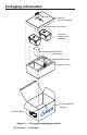
Packaging Information Hex Tool (plastic wrapped) Top Foam Speakers (each plastic wrapped) Wall Mount Assemblies Speaker Rear Cover Bottom Foam Thick Single Wall Packing Product Label Inst Par all t No . 33XX 206W XX X-XX Cei X-01 ling XX -01 RE Sp eake r V.
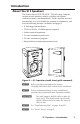
Introduction About the SI 3 Speakers The Extron System INTEGRATOR ™ SI 3 full range, compact, surface mount speaker is ideally suited for classrooms, conference rooms, and boardrooms. With a weather resistant construction, it is also suitable for outdoor environments, and has the following features (see below and page 2).
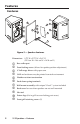
Features Features 5 6 1 11 10 7 2 8 3 4 9 Figure 3 — Speaker features Dimensions: 8.75" H x 5.75" W x 5.61" D (22.2 cm H x 14.6 cm W x 14.
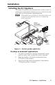
Installation Installing the SI 3 Speakers The Extron SI 3 speakers can be mounted on a surface, such as a wall or post, or mounted in a bookcase, or on a shelf, and can be used with any Extron product supporting audio. N If the speakers are to be placed on a horizontal surface such as a desk or shelf, attach the back cover to enhance the speaker appearance.
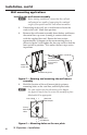
Installation, cont’d Wall mounting applications Installing the wall mount assembly N Before starting installation, ensure that the wall and wall material are capable of supporting the combined weight of the speakers and the wall mount assemblies. 1. If mounting to drywall, use a stud locator to locate the studs in the wall. Mark their position. 2. Remove the wall mount assembly from the box and loosen the central hex cap screw (turning it counter clockwise) with the supplied hex tool.
4. Mark the wall where the wire will pass through the plate, and cut a small access hole large enough for the wire to pass through without interference. Where the stud is wider than the plate's access hole, cut the hole in the wall to the left or right and directly alongside the stud (see figure 7). N 5. Before cutting the hole in the wall, make sure the plate will hide the hole after installation.
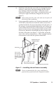
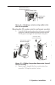
Installation, cont’d 6. Pull sufficient wire up through the holes in the rear plate (see figure 8) to allow ease of connection to the speaker after installation. Do not strip and connect the wire at this time. N Line of Stud Pass the wires through the plate access hole. Figure 8 — Passing the wire through the plate 7.
Anchor this end to a suitable secure point. Seismic Safety Cable Attach cable here and secure it. Figure 9 — Attaching a seismic safety cable to the rear of the speaker Mounting the SI 3 speaker onto the wall mount assembly 3. Carefully lift the speaker above the wall mount assembly and gently slide the speaker box bracket down into the V-Lock groove (see figure 10) until it locks into place. ...and slide it down into the V-lock groove. Lift the speaker up to the wall mount assembly....
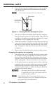
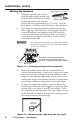
Installation, cont’d Wiring the speakers 1. 2. Strip approx. 15 mm (5/8"). When both speakers are in place, carefully pull enough speaker wire to reach to the terminals at the back Twist the bared wire. of the each speaker and strip the ends of the wire approximately 5/8" (15 mm). Twist the bare strands so that they are held firmly in the connectors. Press down on the spring loaded terminals to open the holes at the top. Observing the correct polarity, (positive wire to , terminal and negative wire to .
5. Insert the hex tool into the locking access, and slightly loosen the hex cap screw. Adjust the speaker to the desired angle (see figure 13), and torque the hex cap screw down clockwise until snug, about 6 to 8 turns. The speaker remains securely in the desired position. Turn clockwise to tighten. Figure 13 — Adjusting speaker and locking in place N 6. Check that the speaker is secure and cannot be lifted from the wall mount assembly after locking it into place.
Troubleshooting Tips To refit the grill: 1. Carefully press the grill back into place. 2. Insert and tighten down the screws. 3. Replace the logo. Securing the grill (optional) If the speaker makes the grill vibrate and creates unwanted noise when in use, it can be secured to the speaker enclosure using the supplied pack of putty. To secure the grill, do the following: 1. After removing the grill, press four pieces of putty onto the outer edges of the grill, one on each edge (see figure 15).
Observed Problem Possible Cause(s) Remedial Action 1 Speaker easily lifted from mount assembly Locking hex cap screw not tightened enough Following the steps on page 9, tighten the hex cap screw until it is not possible to remove the speaker. 2 No sound heard from speakers Speaker cables not connected or damaged Reconnect or replace speaker cable. Check cable routing. Output device (e.g., amplifier) Check that the output devices are plugged in and powered on.
Specifications Audio/acoustic and electrical Speaker type.................................... Indoor/outdoor surface mount speaker Frequency range............................. 75 Hz to 18 kHz, -10 dB, half space Power capacity............................... 16 W continuous pink noise 32 W continuous program Nominal sensitivity........................ 83 dB SPL, 1W, 1m, half space Nominal impedance...................... 8 ohms Driver............................................... 3" (76.
Extron’s Warranty Extron Electronics warrants this product against defects in materials and workmanship for a period of five years from the date of purchase.
www.extron.com Extron Electronics, USA 1230 South Lewis Street Anaheim, CA 92805 800.633.9876 714.491.1500 FAX 714.491.1517 Extron Electronics, Europe Beeldschermweg 6C 3821 AH Amersfoort, The Netherlands +800.3987.6673 +31.33.453.4040 FAX +31.33.453.4050 Extron Electronics, Asia 135 Joo Seng Rd. #04-01 PM Industrial Bldg., Singapore 368363 +800.7339.8766 +65.6383.4400 FAX +65.6383.4664 © 2007 Extron Electronics. All rights reserved.