
User Manual
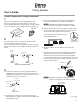

Frame Construction Ceiling Installation
1
Take the cutout template from the packaging box and
punch out along the larger perforated circle. Place the
cutout template against the ceiling and trace along the inside
circle. Carefully cut out the ceiling material along the circle.
3
Cut material.
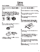
SI 3C LP
Ceiling Speaker
a. Remove the top terminal cover (see the illlustration in
step 3f) by loosening (do not remove) both top screws,
sliding the top terminal cover away from the screws, and
removing the cover, as shown here.
68-1469-01 Rev. B
11 07
User’s Guide
2
The side terminal cover, as shown in step 3f, must first
be removed before wiring the speaker.
Loosen the single top screw of the side terminal cover and
pull the side terminal cover straight out. See the illustration
below.
Side View of Input Terminal
Top Terminal
Cover
Loosen
screw.
Loosen
two screws.
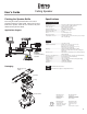
c. Insert the conduit(s) into the knockout opening(s) and
secure the conduit to the cover with the locking nut.
d. Pull the speaker wires from the conduit, strip 0.2" (5 mm)
from the wire ends (do not tin the wires), and secure the
wires into the 4-pole captive screw connector.
To connect speakers in parallel, see the
wiring diagram below.
e. Bring the speaker up to the bottom of the hole in the
ceiling.
f. Plug the wired connector from step 3d into the speaker’s
audio input connector. Secure the top terminal cover
with the two top screws that were loosened in step 3a;
hook the side terminal cover to the top terminal cover; and
secure the side terminal cover in place with the screw that
was loosened in step 2.
1
Power Amplifier
Speaker 1 Speaker 2
Trace template.
Side Terminal
Cover
N Installation in a plenum-rated environment
requires a wire gauge of 14 AWG to 18 AWG.
Top Terminal
Cover
Side Terminal
Cover
See NOTE below.
b. Remove the knockout(s) from the top terminal cover
depending on the direction from which the conduit(s) will
be entering the cover.
Front View of Input Terminal
4-pole Captive
Screw Connector
LOOP IN LOOP
IN
33-1351-01
Rev. B
N Installation in a plenum-rated environment
requires a wire gauge of 14 AWG to 18 AWG.
Knockout
4-pole Captive
Screw Connector