User Guide Streaming AV Products SME 100 H.264 Streaming Media Encoder 68-2167-01 Rev.
Safety Instructions Safety Instructions • English WARNING: This symbol, , when used on the product, is intended to alert the user of the presence of uninsulated dangerous voltage within the product’s enclosure that may present a risk of electric shock. ATTENTION: This symbol, , when used on the product, is intended to alert the user of important operating and maintenance (servicing) instructions in the literature provided with the equipment.
FCC Class A Notice This equipment has been tested and found to comply with the limits for a Class A digital device, pursuant to part 15 of the FCC rules. The Class A limits provide reasonable protection against harmful interference when the equipment is operated in a commercial environment. This equipment generates, uses, and can radiate radio frequency energy and, if not installed and used in accordance with the user guide, may cause harmful interference to radio communications.
Conventions Used in this Guide Notifications The following notifications are used in this guide: DANGER: A danger indicates a situation that will result in death or severe injury. WARNING: A warning indicates a situation that has the potential to result in death or severe injury. CAUTION: A caution indicates a situation that may result in minor injury. ATTENTION: Attention indicates a situation that may damage or destroy the product or associated equipment.
Contents Introduction............................................................ 1 About this Guide.................................................. 1 About the SME 100............................................. 1 Licensed Third-party Software Used in the SME 100........................................................ 2 Suggested PC Requirements........................... 3 Features.............................................................. 4 Definitions..............................................
Backup / Restore Page...................................... 74 Backing Up the SME 100 Using Backup All.......................................... 75 Restoring Config Files from the Backup......... 75 Restoring the Configuration from Another SME 100................................. 75 Control Page..................................................... 77 Creating Audio Breakaway Inputs.................. 81 User and Input Presets.................................. 82 Web-based Configuration Page.................
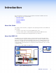
Introduction This section gives an overview of the user guide and describes the SME 100 and its features. Topics that are covered include: • About this Guide • About the SME 100 • Features • Definitions About this Guide This guide contains installation, configuration, and operating information for the SME 100. In this guide: • The term "codec" refers to the H.264 / MPEG-4 AVC codec.
Two versions of the SME 100 are available. • SME 100 HD (part number 60-1061-01) • SME 100 SD (part number 60-1061-02) NOTE: Both versions have similar front and rear panel features and function exactly the same. The difference is that the SD version only supports standard definition output rates. For additional information on supported output rates, see the "Encoder Config Menu" section on page 33.
Licensed Third-party Software Used in the SME 100 Package License Package License kernel General Public License (GPL) v2 e2fsprogs General Public License (GPL) v2 glib2 Lesser General Public License (LGPL) php PHP License v3.
Features • Streams DVI, RGB, HDTV, and video signals with audio over IP networks. • Inputs — DVI-D with loop-through; universal 15-pin HD input with loop-through for RGB, HD component video, S-video, or composite video; BNCs with loop-throughs for component video, S-video, or composite video. • Outputs — Ethernet for streaming H.264 / MPEG-4 AVC encoded video. • Standards-based H.264 / MPEG-4 AVC video compression — The SME 100 employs high, main, and baseline profiles of the H.
• Auto Input Memory — When activated, the SME 100 automatically stores size, position, and picture settings based on the incoming signal. When the same signal is detected again, these image settings are automatically recalled from memory. • EDID Minder® — Automatically manages EDID (Extended Display Identification Data) communication with connected DVI and VGA input sources.
• Embedded preview window — The SME 100 provides an intuitive interface that contains an embedded video window used for viewing live streams. • Embedded web page HTML — The SME 100 interface includes basic HTML code that can be copied and pasted to quickly create web pages for viewing SME 100 AV streams on networked PCs. • RS-232 control port — Using serial commands, the SME 100 can be controlled and configured via DataViewer or integrated into a control system.
Definitions Advanced Audio Coding (AAC) — A standardized compression and encoding scheme for lossy (low quality) digital audio. Advanced Video Coding (AVC) — See the H.264 (MPEG-4 AVC) definition. Bandwidth — A measure of available (or used) data communication resources in bit / s. Bit rate — The number of bits that are conveyed or processed per unit of time.
Hypertext Transfer Protocol over Secure Sockets Layer (HTTPS) — A networking protocol that allows web servers to transfer and display web content to users securely. All transferred data is encrypted so that only the recipient is able to access and read the content. Internet Group Management Protocol (IGMP) — A TCP/IP communications protocol used by hosts and adjacent routers on a network to establish multicast group memberships. Internet Protocol (IP) — The primary protocol that establishes the Internet.
Real-time Transport Protocol (RTP) — An Internet Engineering Task Force (IETF) standard for streaming real-time multimedia over IP in packets. Router — A network device that forwards packets from one network to another. Session Announcement Protocol (SAP) — Used for broadcasting multicast or unicast session information. The SAP periodically multicasts session description information on an industry standard multicast address and port.
Trivial File Transfer Protocol (TFTP) — A file transfer protocol that is generally used to transfer configuration or boot files between devices in a local environment. Unicast — The sending of messages to a single network destination host on a packet-switching network. Basically, N clients of a unicast stream will require the server to produce N streams of unicast data. User Datagram Protocol (UDP) — A connectionless protocol that sends packets across networks using "best-effort" delivery.
Panels and Cabling This section provides information on: • Front Panel Features • Rear Panel Features • Hardware Setup Overview • SME 100 Power Up Procedure Front Panel Features The front panel of the SME 100 is shown in figure 3 below. 1 2 3 4 MENU NEXT 5 6 ADJUST 1 2 3 CONFIG SME 100 STREAMING MEDIA ENCODER Figure 3. a b SME 100 Front Panel Config port — Connect a control PC or other USB device to this port using a Mini-B USB cable (not supplied).
e LCD display — This display shows the device settings and menu configuration information. For information on the LCD display, see the "SME 100 Power Up Procedure" section on page 18 and "Accessing the Menus on the LCD Display" section on page 23. f Adjust knobs — These knobs are used with the menu and next buttons to adjust the settings of the configuration submenus.
e 15-pin HD buffered loop connector (optional) — Connect a video output device to the 15-pin HD buffered loop connector. This connector outputs the input device that is connected to input 2 (d). See figure 6 on the previous page for pin configurations. f DVI connector with EDID emulation (Input 3) — Connect a high resolution digital input device to the DVI connector. g DVI buffered loop connector (optional) — Connect a high resolution digital output device to the DVI buffered loop connector.
j RS-232 connector (optional) — Connect a host computer or control system to the RS-232 connector. Use this port to send Simple Instruction Set (SIS™) commands to the SME 100 for device configuration and control. The default protocol for this port is 9600 baud rate, no parity bit, 8 data bits, 1 stop bit, and no flow control (handshaking).
Resetting the SME 100 Using the Rear Panel The Reset button on the rear panel of the SME 100 is used to reset the SME 100. To select different reset levels, use a pointed stylus or small screwdriver to press and hold the Reset button while the SME 100 is running or press and hold the Reset button while applying power to the SME 100. ATTENTION: Review the reset modes carefully. Using the wrong reset mode may delete important information and configuration settings.
SME 100 Reset Mode Summary Result Purpose and Notes 1 Hold in the recessed Reset button while applying power to the unit. The SME 100 reverts to the factory default firmware for a single power cycle. 4 Hold in the Reset button for about 6 seconds until the Power LED blinks twice (once at 3 seconds, again at 6 seconds). Then, release and press Reset again within 1 second*.
Hardware Setup Overview 1. Turn off and disconnect the SME 100 and all existing devices. 2. Mount the SME 100, if necessary, as described in the “Mounting” section on page 178. 3. Connect one end of an RJ-45 cable to the rear panel Ethernet connector on the SME 100 (see "Rear Panel Features" on page 12). Connect the other end of the RJ‑45 cable to a router or switch to connect the SME 100 to a network. 4.
SME 100 Power Up Procedure NOTE: Before powering on the SME 100, ensure that all necessary devices are powered on and connected properly. Apply power to the SME 100 by connecting a standard IEC power cord into the AC power connector (see the "Rear Panel Features" section on page 12) and plug it to a 100 to 240 VAC, 50 Hz or 60 Hz power source. The SME 100 undergoes a self testing sequence (see figure 12). Power On 2 sec. EXTRON ELECTRONICS SME 100 HD/SD FW V2.00 ~4 sec. 30 sec.
SME 100 Network Configuration This section provides information on: • Network Settings Configuration • SME 100 IP Addressing for Multiple Installations • Protocols Used for Streaming Network Settings Configuration NOTE: See the "IP Addressing" section on page 166 for information on choosing compatible network addresses. The SME 100 is pre-configured with the following network settings. IP address: Subnet mask: Gateway: 192.168.254.254 255.255.0.0 0.0.0.
Protocols Used for Streaming The following transport layer protocols are used for streaming. Pull Push Unicast Multicast Unicast Multicast RTP (RTP over UDP) RTP (RTP over UDP) TS/UDP TS/UDP TS/RTP TS/RTP ES/RTP (Native RTP) ES/RTP (Native RTP) The transport protocols are summarized in this section. For information on how to change the SME 100 transport protocol, see the "Encoder Config Menu" section on page 33.
Multiple SME 100 Devices Using Multicast Streaming When there are more than one SME 100 devices attempting to multicast, they must use unique multicast IP addresses or port numbers (see "Multicast IP Addressing for Multiple SME 100 Installations" on page 169 for additional information). Unicast Streaming Method — An Overview This streaming method is used for on-demand video with low latency and uses a variety of streaming protocols.
Front Panel Operation This section details how to operate and configure the SME 100 using the front panel and the menus available on the LCD display. NOTES: • For information on operating and configuring the SME 100 using the web-based user interface, see the "Web-based User Interface Operation" section on page 46. • For information on operating and configuring the SME 100 using SIS commands, see the "Remote Communication and Control" section on page 117.
Accessing the Menus on the LCD Display To access the primary menus and submenus using the front panel, follow the procedure below while referring to figure 15 on the previous page and the "Front Panel Features" section on page 11. 1. Press the Menu button to access the primary configuration menus. The first menu (Presets) is shown on the LCD display. 2. To choose a primary configuration menu, repeatedly press the Menu button until the desired menu is shown on the LCD display. 3.
User Presets NOTES: • For information on recalling and saving user presets using the web-based user interface, see the "Control Page" section on page 77. • For information on recalling and saving user presets using SIS commands, see "User presets (DVI, RGB, and YUV inputs only)" on page 140 of the "Command and Response Table for SIS Commands" section. User presets are used when a shortcut is needed to quickly recall a group of settings that relate to the current content or current input.
Encode Presets Encode presets save or recall current settings for the encoder. The Encode Rcall and Encode Save menus shown in figure 16 on page 23 are used to recall and save encoder presets. The Encode Save menu creates presets by saving the current set of streaming parameters for the current output stream. The Stream Rcall menu recalls and applies a saved preset to the current output stream. Sixteen available streaming presets are used to recall or save settings.
Streaming Presets NOTES: • For information on recalling and saving streaming presets using the web-based user interface, see the "Using Streaming Presets" section on page 97. • For information on recalling and saving streaming presets using SIS commands, see "Streaming presets" on page 140 of the "Command and Response Table for SIS Commands" section. • Streaming presets are used in the push configuration only.
• Input #N (input video signal type) — This submenu is used to select a video signal type for the currently selected input. N represents the selected input (1, 2, or 3). To use this submenu: • • Rotate either Adjust knob to select a video signal type for the currently selected input. See the "Available Input Video Signal Types" section on page 30 for information on supported video signal types.
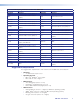
The table on the next page details the resolutions and refresh rates that are available for EDID emulation and supported by the SME 100. NOTES: • There are 24 predefined EDID and 6 custom EDID available. • Custom EDID is captured from devices attached to the 15-pin HD or DVI buffered loop connectors (see the "Rear Panel Features" section on page 12) and stored in the selected custom EDID slot. Custom 1, 2, and 3 capture EDID from the 15-pin HD buffered loop connector.
EDID Emulation Table 50 Hz 60 Hz 640x480 X X 800x600 X X 852x480 X X *1024x768 X *X 1280x768 X X 1280x800 X X 1280x1024 X X 1360x765 X X 1360x768 X X 1365x768 X X 1366x768 X X 1400x1050 X X 1440x900 X X 1600x1200 X X 1680x1050 X X 1920x1200 X X Resolution 24 Hz 25 Hz 30 Hz 75 Hz X 480p 576p X 720p X X 1080i X X 1080p X X Custom 1 Custom 2 Custom 3 Custom 4 Custom 5 Custom 6 NOTES: • * = Default video signal type • The default refresh rate of
Available Input Video Signal Types The Input #N submenu is used to select a video signal type for the currently selected input. Each input supports different video signal types as shown in the table below.
Picture Control Menu The Picture Control menu is used to adjust the video image for the currently selected input. Figure 18 and the information that follows provides an overview of the submenus and the options that are available. INPUT CONFIG Menu PICTURE CONTROL Next H POS V 00000 00000 Horizontal Position Select a horizontal position for the left edge of the active video. Next Next Vertical Position Select a vertical position for the top edge of the active video.
• Color and Tint — This submenu is used to adjust the color and tint of the active video for the selected input. NOTES: • The color adjustment is only available for composite, S-video, and YUVi video signal inputs. • The tint adjustment is only available for composite NTSC and S-video NTSC video signal inputs. Tint is not available for PAL video signal inputs. To use this submenu: • • Rotate the horizontal ([) Adjust knob to adjust the color of the video for the selected input.
Encoder Config Menu The Encoder Config menu is used to configure what is streamed (video and audio; video only) and how the stream is output. Figure 19 and the information that follows provides an overview of the submenus and the options that are available. PICTURE CONTROL Menu ENCODER CONFIG Next STREAM MODE VIDEO / AUDIO Stream Mode Select the stream mode: • Video / Audio • Video only IN# LEVEL Next 0 dB Gain/Attenuation Select the audio level.
Supported Output Resolutions Version Resolution Aspect HD / SD 166x120 4:3 HD / SD 176x144 4:3 HD / SD 320x240 4:3 HD / SD 352x288 4:3 HD / SD 480x320 3:2 HD / SD 480x360 4:3 HD / SD 640x360 16:9 HD / SD *640x480 4:3 HD / SD 720x480 4:3 HD / SD 800x480 5:3 HD / SD 720x576 4:3 HD 800x600 4:3 HD 1024x768 4:3 HD 1280x720 16:9 HD 1920x1080 16:9 NOTE: * = Default output resolution • Vid Bitrate (video bit rate) — This submenu is used to adjust the number of video
Stream Config Menu The Stream Config menu is used to configure how the SME 100 streams to an output device. The SME 100 operates in "push" or "pull" mode depending on the stream method selected. Figure 20 and the information that follows provides an overview of the submenus and the options that are available. MULTICAST STREAM STRM SELECT Next STREAM Next STRM CONTROL STRM METHOD Menu STREAM CONFIG ENABLE to start stream, DISABLE to stop.
Advanced Config Menu The Advanced Config menu is used to configure various settings (auto memory, auto-image™, aspect ratio, OSD label), enable test patterns, and reset the SME 100. Figure 21 and the information that follows provides an overview of the submenus and the options that are available. ADVANCED CONFIG Menu ADVANCED CONFIG Next AUTO IMAGE IN#N ON Auto Image Turn auto image on or off. Next RESET NONE Reset Reboots the unit.
• OSD Label — This submenu is used to set the amount of time that the on-screen label is shown on the output display. When an input is selected, the on-screen label appears as small white text that is placed on a black background in the top left corner of the display window. This configuration option is applied to all of the streams (inputs) on the SME 100. To use this submenu: • • Rotate either Adjust knob to change the amount of time that the OSD label is shown on the output display.
About the Auto Memory Submenu NOTE: For information on using the web-based user interface to enable or disable the auto memory feature, see the "Encoder Settings Page" section on page 88. When the Auto Memory submenu is set to On (default), the SME 100 stores the picture settings of the incoming signal that is connected to each input. When the same input signal is detected again, the stored picture settings are recalled from memory and are automatically applied to the appropriate input.
The Auto Image and Auto Memory submenus affect each other depending on whether they are enabled or disabled. Refer to the table below for more details. NOTE: If the settings obtained from the auto memory feature are not to be used on an input signal, disable auto memory before using the auto-image feature. The table below details the possible combinations of auto-image and auto memory settings.
About the Auto Image Submenu NOTES: • When the auto-image feature is enabled and a new input signal is detected, the SME 100 first attempts to apply values that were stored in auto memory to the input signal (if the auto memory feature is enabled). If no auto memory exists, values that are obtained from the auto-image feature are applied to the new input signal.
About the Aspect Ratio Submenu NOTES: • For information on setting the aspect ratio using the web-based user interface, see the "Encoder Settings Page" section on page 88. • For information on setting the aspect ratio using SIS commands, see "Input aspect ratio" on page 142 in the "Command and Response Table for SIS Commands" section. The Aspect Ratio submenu contains two configuration options. • When the Aspect Ratio submenu is set to Fill (default), the input signal fills the entire output area.
NOTES: • The Color Bars test pattern is used to calibrate color settings on the output display and confirm that the system is properly wired. • The Pulse test pattern (not shown) is used to determine audio functionality. This audio test pattern is a once a second audio pulse of 400 Hz at –10 dBu. • The Timestamp test pattern (not shown) is an on-screen label that appears as small white text on a black background in the top left corner of the output display window.
Comm Settings Menu View Comm Settings The View Comm Settings menu is used to view the current communication port settings. Figure 23 and the information that follows, provides an overview of the submenus available. ADVANCED CONFIG Menu VIEW COMM SETTINGS Next SERIAL PORT 9600 RS232 Next MAC ADDRESS 0005A605BEC3 Serial Port View the baud rate and port protocol of the unit. Next G M S M Gateway Address View the gateway address of the unit.
3. Press and hold the Next button and the Input 3 button simultaneously for approximately three seconds. This changes the View Comm Settings menu to the Edit Comm Settings menu. 4. Press the Next button repeatedly to cycle to the IP address (IP), subnet mask (SM), and default gateway (GM) submenus (see figure 25). VIEW COMM SETTINGS Next + Input 3 EDIT COMM SETTINGS Next SERIAL PORT 9600 RS232 Select Octet Next Change Value Valid addresses are 0 – 254. Figure 25.
Using the Front Panel Lock (Executive Mode) To prevent accidental changes to settings, enable the front panel lock (executive mode) on the SME 100 by pressing the Menu and Next buttons simultaneously for two seconds. The front panel lock disables all of the front panel controls, but allows communication and control changes through the RS-232 connector, Config port, and the web-based user interface.
Web-based User Interface Operation This section provides information about: • Overview of the Web-based User Interface • SME 100 Media Players • Accessing the Web-based User Interface • Live View Page • Installing Media Players • Displayed Video Image Adjustments • Status Page • Configuration Page • File Management Page • Backup / Restore Page • Control Page Overview of the Web-based User Interface The web-based user interface can configure and operate the SME 100.
SME 100 Media Players For optimal performance of the SME 100, Extron recommends two media players depending upon the firmware version. Firmware versions 2.0 and higher use the Extron Streaming Media Player (SMP) (see "Streaming Media Player (SMP) Web Browser Plugin" on page 51). Older firmware versions must use VLC media player and cannot use SMP. NOTE: Extron recommends upgrading older SME 100 devices to firmware version 2.0 or higher and using the SMP web browser plugin for best performance.
Live View Page This is the first page seen after logging in. The page can also be accessed by clicking on the Live View tab (see figure 28). 1 2 3 4 5 6 7 8 9 10 Figure 28. Live View Page The Live View page is used to view and listen to live streams. The Live View page shown in figure 28 contains features that are available when using the SMP web browser plugin. Features of this window can be changed by an administrator using the "Live View Settings Page" on page 98.
2 3 4 5 e 6 7 8 9 10 Stream playback timer — This timer displays the amount of time the user has been streaming live media. Playing a live stream activates the timer. Pressing the Stop button stops the timer and the total streaming time is displayed. NOTE: The timer resets to 00:00:00 whenever the play button is pressed. f Input select button — This button allows the user to switch between live streams. Clicking the button switches inputs (incrementally from 1, 2, 3, and back to 1).
Live View Page Notifications The following notifications may appear on the Live View page: • Starting a stream with the Play icon or Play button displays the initializing... notification, unless the Video Init Time (sec) drop-down menu on the Live View Settings page (see page 98) is set to 0. • Stopping a stream with the Stop button displays the stream stopped notification. • When a stream is disconnected, the disconnected notification is displayed.
Installing Media Players The SME 100 uses a media player plugin to view live streams using a web browser. The Extron SMP web browser plugin is recommended for use with the SME 100 using firmware version 2.0 and higher. VLC media player is used with older 1.0 firmware versions. The following sections describe how to install the media players and plugins to a control PC or viewing device. NOTES: • The procedures presented in the following sections use a Microsoft® Windows® operating system and version 1.
Installing SMP From the SME 100 For new SME 100 devices, install SMP using the File Management page. 1. Open the web-based user interface of the SME 100 (see "Accessing the Web-based User Interface" on page 47). 2. Select the File Management tab, then select SW_Distribution (see figure 31). Figure 31. Select SW Distribution 3. On the next page select Windows (see figure 32). Figure 32.
4. Then select the smp-1.0.0.2-win32.exe file (see figure 33). Figure 33. Select Windows, then SMP Software The SMP installation program launches. 5. When the file download dialog appears, click Run to begin the download (see figure 34). 192.168.254.254 Figure 34. File Download Security Warning 6. When the installation files are downloaded, a security warning dialog box appears. Click Run to begin the installation (see figure 35). Figure 35.
7. When the welcome dialog appears, click on Next to continue the installation (see figure 36). Figure 36. SMP Installer 8. A License Agreement dialog box appears next. Read the agreement, then click Next to continue the installation (see figure 37) . Figure 37.
9. It is recommended to accept the default folder location, but a different location can be entered or selected using the Browse button. to a new location. Click Install when ready (see figure 38). Figure 38. Change Install Location or Install 10. After the installation is complete the following dialog appears. Figure 39. SMP Installation Completed 11. Select Finish to complete the installation. The SMP web browser plugin is now installed. 12. Restart the web browser.
Installing SMP from the Website If the SME 100 firmware was manually upgraded, the SMP web plugin must be downloaded from the Extron website. Use the following procedure to download the latest SMP player browser plugin. 1. Go to www.extron.com and search for the SME 100 product page. 2. Select the Downloads tab, then select the SMP Web Browser Plugin link. 3. Follow the instructions that appear on the screen. 4. The file is saved onto the computer. Note the folder where the firmware file is saved. 5.
Installing VLC Media Player Stored on the SME 100 (FW 1.0 Only) When using firmware versions older than FW 2.0, VLC media player must be installed. SMP will not function with older firmware versions. NOTE: Extron recommends upgrading all SME 100 devices to the latest firmware and using SMP as the default web browser plugin. Use the following procedure to install VLC media player (version 1.1.10). 1. Access the web-based user interface of the SME 100 (see "Accessing the Web‑based User Interface" on page 47).
3. A File Download window appears. Click Run to download and start the VLC media player installation (see figure 42). Figure 42. File Download Window NOTE: The file can also be saved to the control PC or viewing device by pressing the Save button. After the file has been saved, navigate to the executable software file and double-click it to start the VLC media player installation. 4. A Security Warning window may appear that warns about running an unknown application.
6. The VLC media player installer welcome window appears. Click Next (see figure 45). Figure 45. VLC Media Player Installer Welcome Window 7. The VLC media player agreement window appears. Read over the agreement and license terms. To accept the agreement, click Next (see figure 46). Figure 46.
8. The VLC media player components window appears (see figure 47). Make sure the Full option is selected from the Select the type of install drop-down menu. Click Next. NOTE: Compatibility issues between the SME 100 and the VLC media player plugin may occur if a full installation is not selected. Figure 47. VLC Media Player Components Window 9. The VLC media player install location window appears. If necessary, click on the Browse button to select an installation location for VLC media player.
10. The VLC media player installation will require a few minutes to complete. When installation is complete, the window shown in figure 49 appears. Make sure the Run VLC media player 1.1.10 check box is selected and click Finish. Figure 49. VLC Media Player Install Complete Window 11. VLC media player is launched automatically (when the Run VLC media player check box is selected in the previous step) and the Privacy and Network Policies window appears.
Installing VLC Media Player Using the File Management Page This is an alternate procedure that can be used to install VLC media player (version 1.1.10) to a control PC or viewing device when using firmware version 1.0. 1. If necessary, access the web-based user interface of the SME 100 (see "Accessing the Web-based User Interface" on page 47). 2. Click the File Management tab. The File Management page appears (see figure 51). 2 3 4 Figure 51. File Management Page — Software Distribution 3.
6. From the Windows directory, click on the VLC media player file to start the installation process (see figure 53). 6 Figure 53. vlc-1.1.10-win32.exe File Management Page — VLC media player Install File 7. Proceed to step 3 of the "Installing VLC Media Player Stored on the SME 100" section on page 57. Installing QuickTime Media Player In some cases, a user may want to use QuickTime media player. For Mac computers, QuickTime is the only plugin available. The SME 100 can use version 7.7.
Displayed Video Image Adjustments This section details how to adjust the image of the displayed video when viewed on a control PC or viewing device using a media player. This section focuses on making image adjustments using a control PC or viewing device and a Microsoft® Windows® operating system. The following media players are used: • Extron SMP web browser plugin version 1.0 (SME 100 firmware versions 2.0 and higher) • VLC media player version 1.1.10 or version 2.0.
2. The VLC media player appears. While playing a SME 100 stream (see the "Playing a Stream Using VLC Media Player" section on page 158), from the Tools menu, select Effects and Filters (see figure 54). Figure 54. VLC media player — Effects and Filters 3. The Adjustments and Effects window appears. Click the Video Effects tab and under the Basic tab, select the Image adjust check box (see figure 55). Image settings are now able to be configured. Figure 55.
Using QuickTime Media Player NOTES: • This procedure only affects the image of streamed video that is played back on QuickTime media player. • Image settings should be changed while playing a SME 100 stream using QuickTime media player. To play a stream using QuickTime media player, see the "Playing a Pull Stream Using QuickTime Media Player" section on page 162. Use the following procedure to adjust the image settings of QuickTime media player. 1. Run QuickTime player.
Status Page The Status page is accessed by selecting the Status tab (see figure 57). 1 SME 100 HD / SD 2.00 Mon, 10 Oct 2012 2 SME-100 HD/SD-05-be-3c 192.168.254.254 3 4 Figure 57. Status Page The Status page displays general information about the SME 100. a System Description panel • Model — This field displays the model name of the unit. • Description — This field displays a brief description of the unit. • Part Number — This field displays the part number of the unit.
b c d IP Settings panel • Unit Name — This field displays the network name of the unit. This name can be changed on the System Settings page (see page 85). • IP Address — This field displays the IP address of the unit. The IP address can be changed on the System Settings page (see page 85). • DHCP — This field displays the Dynamic Host Configuration Protocol (DHCP) status. DHCP can be enabled and disabled on the System Settings page (see page 85).
Configuration Page The Configuration page contains eight additional links to pages that are used to configure the general settings of the SME 100. The "Web-based Configuration Page" section on page 84 presents a detailed overview of each configuration page. The following configuration pages are available.
c Filter by File Extension — Use this drop-down menu to view files that contain certain extensions. Only the files that contain the specified extension will be shown. By default, two filters are available. • All — Select this filter to show all of the available files within a directory. • None — Select this filter to hide all of the files within a directory. Only directories are visible when using this filter.
Browsing Directories and Files Use the following guidelines to browse directories and files on the File Management page. • Click on a directory link to view the files stored in the folder (see figure 59). Figure 59. • File Management Page — Directory Links Use the root and back links (see figure 60) to navigate between directories. • Click the root link to go to the root directory ( / ). • Click the back link to go back to the previous directory. Figure 60.
Uploading Files Use the following procedure to upload files to the SME 100. NOTE: If the file uploaded to the SME 100 is larger than the amount of available memory shown in the Bytes Left field, a message appears notifying the user that not enough free space is available to store the file. 1. Navigate to the desired location where files will be uploaded (see the "Browsing Directories and Files" section on page 71 for navigation guidelines). 2.
Managing Files Using FTP The SME 100 can act as an FTP file server. FTP provides an alternate method to accessing the backup files of the SME 100. To manage files on the SME 100 using FTP: 1. From the control PC, open a web browser. 2. In the Address field, enter the IP address of the SME 100 using the following format, ftp://[SME 100 IP address] then press (see figure 65). Figure 65. Enter an FTP Address (shown 192.168.254.254) 3. A Log On As window appears.
Backup / Restore Page The File Management tab also contains a backup and restore page, accessed by clicking on the Backup/Restore link on the left sidebar (see figure 68). Backup / Restore Backup/Restore Backup files are stored in directory “/nortxe-backup”. Backup 1 Backup All - Save IP configuration (ip.cfg) and box-specific parameters (box.cfg) Restore 2 3 IP Config Box-specific - Restore IP configuration - Restore box-specific parameters Figure 68.
Backing Up the SME 100 Using Backup All If a Backup All has never been done, or to do a routine backup of both the IP and Box configuration files: 1. Connect the SME 100 (see "Rear Panel Features" on page 12). 2. Open a web-browser and enter the IP address of the SME 100 (see "Accessing the Web-based User Interface" on page 47). 3. Go to the File Management Tab (see figure 68 on page 74). 4. Select the Backup/Restore link on the left sidebar of the File Management page. 5.
On the donor SME 100 (device D): 1. Complete the procedure "Backing Up the SME 100 using Backup All" on the previous page. If Backup All has already been completed, go to step 2. 2. Open a web-browser. Enter the IP address of device D, then press . 3. Go to the File Management Tab (see figure 68 on page 74). 4. Select the File Management link on the left sidebar of the File Management page. 5. Select the nortxe-backup directory, then select the BOX.CFG file. 6. Save the BOX.
Control Page The Control page is accessed by selecting the Control tab (see figure 69). 1 2 3 4 5 6 7 8 9 Figure 69. Control Page The Control page is used to configure the individual settings of each input. Available settings that can be configured include audio controls, video/picture controls, input sampling controls, and preset controls (saving, recalling, and renaming).
b 2a 2b Player toolbar — The player toolbar provides the following live stream controls. 2c 2d 2e 2f 2g 2h 2i Figure 70. Ç É î ï Live View Player Toolbar Play and Stop button — This button is used to play and stop live streaming media. Volume mute button — This button is used to mute and unmute the audio volume. Volume control — This slider bar is used to adjust audio volume. This control is initially hidden. To reveal this control, hover over the volume mute button.
M Window fullscreen button — This button is used to display the video at the full display resolution and size. NOTE: For information on displaying a stream in full screen mode using other media players, see the "Streaming Playback Methods" section on page 157. O c Closed caption button — This button is used to toggle closed captioning on or off. Audio/Video Controls panel — Input Selection • Input selection buttons — These buttons select (switch) inputs and can be used to create audio breakaway inputs.
e f Audio/Video Controls panel — Audio • Mute button — This button mutes the output audio of the selected input. This button does not stop the output audio stream and does not mute the video. The audio mute feature remains active when other inputs are selected. Clicking the Mute button again removes the audio mute feature. • Gain / Attenuation control — This drop-down menu is used to set the audio level for the currently selected input. The range of settings –15 dB to +15 dB.
g Input Sampling panel To adjust the following picture adjustments, enter the desired value directly into the field or use the or icons to adjust the values by ±1. h • Horizontal Start — This field is used to set the horizontal start position of the active video for the selected input. The default is 128. • Vertical Start — This field is used to set the vertical start position of the active video for the selected input. The default is 128.
User and Input Presets There are two types of presets on this page. • User Presets — User presets are used when a shortcut is needed to quickly recall a group of settings that relate to the current content or current input. The User Presets panel is used to recall and save user presets. Saving a user preset saves the current set of image parameters for the currently selected input. Recalling a user preset recalls and applies a saved preset to the currently selected input.
Saving or recalling presets 1. Select an input using the input selection buttons (see item c on page 79; Input Selection). 2. Select a preset from the desired Preset drop-down menu. 3. Click the Recall button to recall the selected preset. Click the Save button to save the selected preset. NOTE: The preset is not saved or recalled if the Save or Recall button is not clicked. Renaming presets 1. Select an input using the input selection buttons (see item c on page 79; Input Selection). 2.
Web-based Configuration Page The Configuration page contains eight additional pages that are used to configure the general settings of the SME 100. This section presents a detailed overview of each configuration page. The following configuration pages are available.
System Settings Page This is the first page that is seen after clicking on the Configuration tab. This page can also be accessed by clicking on the System Settings link on the left sidebar of the Configuration page (see figure 72). 1 SME-100-HD/SD-05-BE-3C 192.168.254.254 2.00 SME 100 HD/SD 2 3 4 Not Specified Not Specified Figure 72. System Settings Page The System Settings page is used to configure the basic settings of the SME 100.
b • Subnet Mask — This field is used to change the subnet mask address of the unit. Default subnet mask address is 255.255.0.0. • DNS — This field is used to assign the SME 100 to the IP address of a Domain Name System (DNS) server. • DHCP — If Dynamic Host Configuration Protocol (DHCP) in set to On, DHCP will enable a server (that is on the same network as the SME 100) to automatically assign an IP address to the SME 100.
c NTP Settings panel The Network Time Protocol (NTP) is a is used for synchronizing the clocks of computer systems over networks. To enable NTP, click on the Enabled radio button. The SME 100 will then sync its clock to the NTP server that is specified. NOTES: • Fill in the following fields and click the Submit buton, then click the Sync NTP Now button to sync the SME 100 to the specified NTP server.
Encoder Settings Page The Encoder Settings page is accessed by clicking on the Encoder Settings link on the left sidebar of the Configuration page (see figure 73). 1 3 2 4 5 6 8 7 Figure 73. Encoder Settings Page The Encoder Settings page contains configuration settings that affect all streams (except for the configuration settings in the Video Input Configuration panel).
b Video Input Configuration panel • Input — These drop-down menus are used to select a video signal type for each input. Each input supports different video signal types. The table below details the available video signal types for each input.
c Encoder Configuration panel • Resolution — This drop-down menu is used to set the resolution of the video being output (streamed) by the SME 100. The table on page 34 of the "Encoder Config Menu" section lists output resolutions that are supported by the SME 100. • Frame Rate — This drop-down menu is used to set the frame rate of the video being output (streamed) by the SME 100. The range of settings varies depending on the media player plugin used to view streams. The default is 30 frames per second.
d e • GOP Length — This field is used to specify the number of secondary frames (predictive frames / P-frames) that are used between two primary frames (intraframes / I-frames). A lower GOP length uses more bandwidth since more primary frames are required. A higher GOP length uses less bandwidth since fewer primary frames are required.
• QoS (Differentiated Service) — Quality of Service allows specified network traffic to be guaranteed a certain level of priority. The QoS includes maintaining a specified level of bandwidth, latency, and packet loss. QoS allows for control of the bandwidth in a network resulting in greater reliability. Differentiated Services Code Point (DSCP), or Diffserv (RFC 2474), is used for classifying network traffic and providing QoS.
f Advanced Configuration panel • OSD Duration — This drop-down menu is used to set the amount of time (in seconds) that the on-screen label is shown on the output display. When an input is selected, the on-screen label appears as small white text that is placed on a black background in the top left corner of the display window. The range of settings is 0 to 5. The default is 2. • Test Pattern — This drop-down menu is used to select test patterns which are used to calibrate display devices.
Universal OSD Configuration panel This portion of the advanced configuration panel is used to configure the information that is seen when viewing the universal OSD test pattern / label. The universal OSD test pattern / label is an on-screen label that appears as small white text that is placed on a black background in the top left corner of the output display window. The table below and on the next page lists the status information that can be selected in the Information drop-down menus.
Selectable Status Information Status Information Description # Users The number of users that are connected to the SME 100 is displayed. CPU Usage The percentage of central processing unit (CPU) that is being used is displayed. For example, if the number 37 is shown, 37 percent of the CPU on the SME 100 is currently being used. CPU Idle The percentage of central processing unit (CPU) that is available is displayed.
Using Encoding Presets The Encoding Presets panel is used to recall and save presets. Saving a preset saves the current set of encoding parameters for the current output stream. Recalling a preset recalls and applies a saved preset to the current output stream. Encoding presets allow the user to quickly switch between various encoder profiles based on the target resolution or bit rate. Sixteen available encoding presets are used to recall or save settings.
Renaming an encoding preset 1. Select the desired encoding preset from the Preset drop-down menu . 2. Rename the encoding preset using the Rename Preset field (16 characters maximum). 3. Click the Rename button to save the encoding preset name. Click the Cancel button or navigate to a different web page to clear any changes that were made. Using Streaming Presets The Streaming Presets panel is used to recall and save presets.
Live View Settings Page The Live View Settings page is accessed by clicking on the Live View Settings link on the left sidebar of the Configuration page (see figure 74). 1 2 3 4 5 Figure 74. Live View Settings Page The Live View Settings page is used to configure how a stream is viewed on the Live View page. Available configuration options include media player selection (SMP, VLC media player or QuickTime), toolbar settings, and live view page timeout settings.
To use this page, click on the Select Role to Edit drop-down menu and click on the desired role that requires editing. Two roles are available for editing. • Admin — Select this role to edit the Live View page seen by administrators. • Viewer — Select this role to edit the Live View page seen by viewers / users. Each role contains the following configuration options. a VLC/SMP Specific panel NOTE: This panel is grayed out if the QuickTime player is selected as the default media player.
c Page Timeout panel This panel is used to automatically close (log out) the connection between the viewer and the SME 100 after a specified amount of idle time has passed. This feature helps manage available bandwidth, especially when a large amount of users are accessing the SME 100 to view streams. A setting of 0 hours and 0 minutes means the timeout feature on the Live View page is disabled.
Embedding the SME 100 Stream The Embed VLC / SMP / QuickTime panel (see e in figure 74) on the Live View Settings page creates HTML code that can be placed into customized web pages. Before placing this code into a web page, make sure that all of the settings on the SME 100 have been properly configured and that the stream is viewable from the Live View page. NOTES: • Embedded streams will not work if a user password is required to access the stream.
6. Navigate to the desired save location (see figure 78). a. In the File name field, enter the desired name for the Notepad document. Make sure the name of the file contains a .html extension (see figure 78 for an example). The name of the file must not contain a .txt extension. b. From the Save as type drop-down menu, make sure All Files is selected. c. Click Save. The Notepad document is now saved as an HTML document. Figure 78. Saving the Notepad Document 7.
Port Settings Page The Port Settings page is accessed by clicking on the Port Settings link on the left sidebar of the Configuration page (see figure 80). 1 2 Figure 80. Port Settings Page The Port Settings page is used to change the settings of the serial port and the network port. These ports are used to communicate with the SME 100 using a control PC or control device.
b • Baud Rate — This drop-down menu is used to set the baud rate that is used for communication with the SME 100. The default is 9600. • Stop Bits — This drop-down menu is used to set the number of stop bits that are used for communication with the SME 100. The default is 1. • Parity — This drop-down menu is used to set the parity that is used for communication with the SME 100. The default is None.
Advanced Settings Page The Advanced Settings page is accessed by clicking on the Advanced Settings link on the left sidebar of the Configuration page (see figure 81). Figure 81. Advanced Settings Page The Advanced Settings page is used to load or save EDID settings and sync the SME 100 to a matrix switcher. a EDID panel NOTES: • After all of the necessary changes have been made to the following configuration options in this panel, click the Load button to load the EDID to the selected input device.
b Sync-To-Matrix panel NOTES: • After all of the necessary changes have been made to the following configuration options in this panel, click the Submit button to save the configuration settings. Clicking the Cancel button or navigating to a different web page clears any changes that were made. • The SME 100 cannot be synced to an SMX matrix switcher. • For information on syncing the SME 100 to a matrix switcher, see the "Matrix Switcher Syncing" section on page 109.
Creating a Custom EDID Use the following procedure to create a custom EDID using the Advanced Settings page on the SME 100 (see figure 82). Figure 82. Advanced Settings Page — Creating a Custom EDID 1. Connect a video output device to the 15-pin HD buffered loop connector (buffered input 2) or the DVI buffered loop connector (buffered input 3) located on the rear panel of the SME 100 (see the "Rear Panel Features" section on page 12). 2.
Applying an EDID to an Input Device Use the following procedure to apply an EDID to an input device connected to the SME 100 using the Advanced Settings page (see figure 83). 2 3 4 5 Figure 83. Advanced Settings Page — Applying EDID 1. If necessary, connect an input device to the 15-pin HD connector (input 2) or the DVI connector (input 3) located on the rear panel of the SME 100 (see the "Rear Panel Features" section on page 12). 2.
Matrix Switcher Syncing Use the following procedure to sync the SME 100 to a matrix switcher. Camera AV Tuner HD Tuner DVD/VCR Combo INPUTS 1 2 3 4 5 6 7 8 9 10 11 12 CONTROL 1 2 3 4 5 6 7 8 ENTER PRESET VIEW IO ESC VIDEO AUDIO OUTPUTS CROSSPOINT ULTRA SERIES ULTRA-WIDEBAND MATRIX SWITCHER WITH ADSP™ Matrix Switcher Document Camera ADJUST BUFFERED LOCAL MONITOR OUTPUT ID PIN 4 ID PIN 11 1 INPUT 2 3 MENU NEXT H.
3. On the SME 100, configure input 2 as follows. a. On the SME 100, switch to input 2 (which is connected to the matrix switcher). b. Set the following configuration settings as desired. These configuration options are all available in the Input Config menu when using the front panel menu system (see the "Input Config Menu" section on page 26). These configuration settings are also on the Control page (see page 77) of the web-based user interface (except for signal type).
4. In the Sync to Matrix panel, select Enabled from the Enabled/Disabled radio buttons (see figure 86). Advanced Settings EDID Sync-To-Matrix 4 5 6 7 8 9 Figure 86. Advanced Settings Page — Sync-To-Matrix 5. Use the Video Out field to enter the number of the matrix switcher video output port connected to the SME 100. 6. Use the IP Address field to enter the IP address of the matrix switcher connected to the SME 100. 7.
Using the Synchronized SME 100 and Matrix Switcher Ensure the following is done when using the SME 100 with the matrix switcher: • Perform all input switching using the matrix switcher. A one second RGB delay on the matrix switcher is recommended to minimize the appearance of a glitch in the output while the SME 100 locks onto the new signal.
Security Page The Security page is accessed by clicking on the Security link on the left sidebar of the Configuration page (see figure 87). Figure 87. Security Page The Security page is used to set password security, create user names, and see which active users are logged into the SME 100. NOTES: • The names of the admin and user profiles cannot be changed. • By default, neither the admin or user profiles are assigned passwords.
a b Passwords panel • User Name — Use this field to enter a user name that will be used to log in. The maximum user name length is 15 characters. User name entries are case sensitive. • Password — Use this field to enter the desired password that will be used to log in. A password is required for all user created user names. The minimum password length is 4 characters. The maximum password length is 12 characters. Password entries are case sensitive.
Firmware Upgrade Page The Firmware Upgrade page is accessed by clicking on the Firmware Upgrade link on the left sidebar of the Configuration page (see figure 89). Figure 89. Firmware Upgrade Page The Firmware Upgrade page is used to upgrade the firmware of the SME 100. NOTES: • The firmware file must have a .eff or .efs file extension. Uploading an incorrect file may cause the SME 100 to stop functioning.
Reset Page The Reset page is accessed by clicking on the Reset link on the left sidebar of the Configuration page (see figure 90). Figure 90. Reset Page The Reset page is used to reset the configuration settings of the SME 100. The SME 100 also reboots after a reset option is selected. • Factory Reset — Click this button to reset all AV and picture controls, presets, and encoder settings to factory defaults.
Remote Communication and Control This section provides information on: • Connecting a Control Device • Software Overview • Simple Instruction Set (SIS™) Control • Command and Response Table for SIS Commands • Power Save Mode Connecting a Control Device The SME 100 can be remotely controlled using one or more of the following methods. • Use a control PC or other device that is connected to the same network as the SME 100.
Software Overview This section details how to initialize the various programs that are used to send SIS commands to the SME 100. Using DataViewer DataViewer is available on the included software disc and also for download, free of charge, from the Extron web site. Downloading the software 1. Go to http://www.extron.com/download. 2. At the Download Center page, click the Software link on the left sidebar menu or click on the Control Software icon (see figure 91). Figure 91.
Installing the software 1. Use the file browser on the PC to navigate to the executable software file and double-click it to open it. 2. Follow the instructions on the Installation Wizard screens to install the software to the computer. Running DataViewer 1. From the desktop, select Start > All Programs > Extron Electronics > IPL Tools > DataViewer > Dataviewer. If a shortcut to DataViewer was placed on the desktop, the software can be opened by double-clicking on the icon. 2.
4. The main DataViewer window appears. Use the Commands field to enter SIS commands and view the responses in the Responses field (see figure 95, below). 2 Enter SIS Commands Figure 95.
Sending commands using an RS-232 connection 1. Use an RS-232 cable to connect a control PC or other RS-232 device to the RS-232 connector located on the rear panel of the SME 100 (see the "Rear Panel Features" section on page 12). 2. Open DataViewer (see the "Running DataViewer" section on page 119). 3. On the Communication Setup window (see figure 96): 3a 3b 3c Figure 96. RS-232 Connection Setup Window a. Select the RS-232 tab. b. Select values for the following fields.
Sending commands using a USB connection 1. Use a Mini-B USB cable to connect a control PC or other USB device to the front panel Config port of the SME 100 (see the "Front Panel Features" section on page 11). NOTE: PCs or USB devices connected to the SME 100 using the config port require a USB driver for communication. If a PC or device is connected to the SME 100 Config Port while DataViewer is installed, the USB driver is loaded automatically. 2. Open DataViewer (see "Running DataViewer" on page 119). 3.
Using Telnet Follow the procedure below to run Telnet. NOTE: To activate and run Telnet in Microsoft® Windows® 7, select Start > Help and Support or see the "Windows 7 Help and How-to" documentation available online. 1. From the desktop, select Start > Run. 2. The Run window appears. In the Open field, type telnet and click OK (see figure 98). Figure 98. Run Program Window 3. The Telnet application appears.
Simple Instruction Set (SIS™) Control Host-to-SME 100 Communications SIS commands consist of one or more characters per field. No special characters are required to begin or end a command sequence. When a command is valid, the SME 100 executes the command and sends a response to the host device. All responses from the SME 100 to the host end with a carriage return and a line feed (CR/LF = ]), which signals the end of the response character string. A string is one or more characters.
Error Responses When the SME 100 receives a valid SIS command, it executes the command and sends a response to the host device. If the SME 100 is unable to execute the command because the command is invalid or it contains invalid parameters, it returns an error response to the host.
Symbol definitions ] = CR/LF (carriage return/line feed) } or ¦ = Carriage return (no line feed, hex 0D) • = Space * = Asterisk character (which is a command character, not a variable) E or W = X! = X@ = X# = Escape Input selection: 1 through 3 (2 and 3 applicable for EDID only) Output selection 2 = Analog only (VGA loop) 3 = Digital only (DVI loop) Input video format 1 = RGB (default) 2 = YUVp / YUV-HD 3 = RGBcvS 4 = YUVi 5 = S-video 6 = Composite 9 = DVI 11 = Autodetect X$ = Horziontal / Vertical
X1( = X2) = X2! = X2@ = X2# X2$ X2% X2^ X2& Pan (default range depends on output resolution) Test Pattern 0 = Off (default) 1 = Color bars 2 = Pulse 3 = Timestamp 4 = Universal OSD 5 = Fine crosshatch 6 = 4x4 Crosshatch 7 = Grayscale (32 level) 8 = Ramp 9 = Alternating pixels 10 = White field 11 = Crop 12 = 1.33 aspect ratio 13 = 1.78 aspect ratio 14 = 1.85 aspect ratio 15 = 2.
X3( = X4) = Aspect ratio settings 1 = Fill (each input rate automatically fills the entire output raster; default) 2 = Follow (each input rate is displayed with its native aspect ratio) Power save mode 0 = Power save mode disabled (default) 1 = Power save mode enabled (power save mode begins when no device activity is detected for seven minutes) X4@ X5) X5! X5@ = Audio delay (ms): 0 through 999 = Maximum video bit rate (kbps): 200 through 10000 (default = 10000) = Video frame rate: 1 through 30 (de
X6^ = X6& = General information query (I commands) 1 = Model name Example: SME 100 HD or SME 100 SD 2 = Model description Example: Extron Electronics MPEG-4/H.
X6* X6( X7) X7^ = EDID resolution = 4 = Custom 1 (analog) 5 = Custom 2 (analog) 6 = Custom 3 (analog) 7 = Custom 4 (digital) 8 = Custom 5 (digital) 9 = Custom 6 (digital) 10 = 640 x 480 11 = 800 x 600 12 = 852 x 480 13 = 1024 x 768 (default) 14 = 1280 x 768 15 = 1280 x 800 16 = 1280 x 1024 17 = 1360 x 765 18 = 1360 x 768 19 = 1365 x 768 20 = 1366 x 768 21 = 1440 x 900 22 = 1400 x 1050 23 = 1680 x 1050 24 = 1600 x 1200 25 = 1920 x 1200 30 = 480p 31 = 576p 32 = 720p 33 = 1080i 34 = 1080p Maximum stream b
X11$ = X11* = X11( = X12@ = IP address: xxx.xxx.xxx.xxx Leading zeros are optional and are suppressed in returned values. Factory default IP address: 192.168.254.254 Factory default gateway IP address: 0.0.0.0 Factory default DNS server IP address: 0.0.0.0 Factory default multicast IP address: 239.199.188.138 Valid multicast IP addresses: 225.0.0.0 through 239.255.255.255 Hardware MAC address: 00-05-A6-xx-xx-xx Subnet mask: xxx.xxx.xxx.xxx Leading zeros are optional and are suppressed in returned values.
X13$ = X14! = X14( = X15@ = Daylight savings time 0 = Off (ignore) 1 = U.S.A. 2 = Europe 3 = Brazil Check password The actual password is not shown. If a password is set, four asterisks (****) are returned. If a password is not set, nothing is returned. Default name: shows the default name of the unit using the model name and the last three pairs of the MAC address. Example: SME-100-HD/SD-00-02-3D Connection security level NOTES: • The response is returned as two digits.
Command and Response Table for SIS Commands Command ASCII Command (host to unit) Response (unit to host) Additional Description Input Configurations Input selection Video and audio X! ! In X! • All ] Select audio and video from input source X!. Video X! & In X! • RGB ] Select video from input source X!. Audio X! $ In X!• Aud ] Select audio from input source X!. View video input & X! ] View currently selected video source. View audio input $ X! ] View currently selected audio source.
ASCII Command (host to unit) Response (unit to host) Enable X!*1A Img X!*1 ] Turn on auto-image for input X!. Disable X!*0A Img X!*0 ] Turn off auto-image for input X!. Execute A Img ] Execute auto-image for the selected input. Execute and fill 1*A Img1 ] Execute auto-image for the selected input and fill the entire output. Execute and follow 2*A Img2 ] Execute auto-image for the selected input and follow the aspect ratio of the input. View X! A X1) ] View the auto-image setting.
Command ASCII Command (host to unit) Response (unit to host) Pixel phase (available only for RGB and YUVp input signals) E X^ PHAS } Specify a value Phas X!*X^ ] Increment value E + PHAS } Decrement value View Additional Description Adjust the pixel phase to the specified value for the active input. Increase the pixel phase. E − PHAS } Phas X!*X^ ] Phas X!*X^ ] E PHAS } X^ ] Show the pixel phase.
Command ASCII Command (host to unit) Response (unit to host) Additional Description Picture Adjustments Video mute Blanks selected input. 0B Vmt1 ] Vmt0 ] B X1) ] View the blanking status. Specify a value E X1% COLR } Sets color level to X1%. Increment value E + COLR } Colr X!*X1% ] Colr X!*X1% ] Decrement value E − COLR } View E COLR } Enable blanking 1B Disable blanking View Displays selected input. Color Increments color level. Colr X!*X1% ] X1% ] Decrements color level.
ASCII Command (host to unit) Response (unit to host) Specify a value E X1^ VCTR } Set vertical centering to X1^. Increment value E + VCTR } Vctr X!*X1^ ] Vctr X!*X1^ ] Decrement value E − VCTR } Shift window up. View E VCTR } Vctr X!*X1^ ] X1^ ] Specify a value E X1& HSIZ } Hsiz X!*X1& ] Set horizontal size (width) to X1&. Increment value E + HSIZ } Hsiz X!*X1& ] Increase the width of the window. Decrement value E − HSIZ } Hsiz X!*X1& ] Decrease the width of the window.
Command ASCII Command (host to unit) Response (unit to host) Additional Description Output Configurations Encoder profile type Set encode profile E X8) EPRO } View encode profile E EPRO } Epro X8) ] X8) ] Set encode profile to X8). View current encode profile. Closed Caption Set CC format E X8@ TVCC } View CC format E TVCC } Tvcc X8@ ] X8@ ] Set CC to X8@. Vres X2! ] X2! ] Set the resolution to X2!. Set the frame rate value to X5!. View current CC status.
ASCII Command (host to unit) Response (unit to host) Set stream mode E X5@ SMOD } Set the stream mode to X5@. View stream mode E SMOD } Smod X5@ ] X5@ ] Brct X5# ] X5# ] Set the bit rate control to X5#. Bitr S X6( ] Set the maximum (total) bit rate value to X6(. X6( ] View the maximum (total) bit rate allowed for streaming. Bitr M X5) ] Set the maximum (total) video bit rate value to X5). X5) ] View the maximum (total) video bit rate allowed for each stream.
Command ASCII Command (host to unit) Response (unit to host) Additional Description Presets User presets (DVI, RGB, and YUV inputs only) Recall preset 1*X2%. Save preset 1*X2%, 1 Rpr X2% ] 1 Spr X2% ] Recalls user preset X2% for the selected input. Saves user preset X2% for the selected input. User preset name NOTE: To clear a user preset name, a single space character should be entered for X1$. This action resets the user name back to the default setting.
ASCII Command (host to unit) Response (unit to host) Additional Description Save preset 3*X8#. 4*X8#, 4RprX8# ] 4SprX8# ] Recalls encode preset X8#. Saves encode preset X8#. Delete/clear preset E X4*X8# PRST } Prst X4*X8# ] Clears encode preset X8# and sets encode preset X8# name to [unassigned]. PNAM 4*X8# *X1$ ] Set the name ( X1$ ) for encode preset X8# . E 4*X8# PNAM } X1$ ] E X4*X8# PRST } Prst X4*X8# ] View the name of encode preset X8#.
ASCII Command (host to unit) Response (unit to host) Set audio bit rate E A X6$ BITR } Bitr A X6$ ] Set the audio bit rate value of the output to X6$. View E A BITR } X6$ ] View the currently set output bit rate separated values. Set sample rate E X6% AUSR } Ausr X6% ] Set the audio sample rate value of the output to X6%. View E AUSR } X6% ] View the currently set sample rate value. Set the test pattern to X2). Set input X! to always fill the entire output raster (default).
Command ASCII Command (host to unit) Response (unit to host) Additional Description Port Configuration Serial data port (RS-232) Configure parameters E X10!*X12%,X12^,X12&, X12* CP } View parameters E X10! CP } Cpn X10! • Ccp X12%,X12^, X12&,X12* ] X12%,X12^,X12&,X12* ] Configure mode E X10!*X12( CY } Cpn X10! • Cty X12( ] Configures the mode of the serial data port. The SME 100 only supports RS-232. View mode E X10! CY } X12( ] View the mode of the serial data port.
Command ASCII Command (host to unit) Response (unit to host) Additional Description Port Assignment NOTES: • Duplicate port# assignments are not permitted (for example, the telnet and web port assignment cannot be the same) and will return the E13 error. • Remapping of port# assignments must be to ports 1024 or higher (unless resetting to the default port number or disabling the port by setting it to 0).
Command ASCII Command (host to unit) RTP port (streaming media port selection) E R[start port#]* Set RTP range port [end port#]PMAP } map Response (unit to host) Additional Description Pmap R[start port#]* [end port#]] Set the RTP port range. Reset RTP range port map E R[port#]PMAP } Pmap R 50000*50999 ] Reset the RTP port range to default (50000-50999). Disable RTP ports E R 0PMAP } Disable all RTP ports.
Command ASCII Command (host to unit) Response (unit to host) E LSTP } TCP Listening ports on IPV4 and IPV6:] [port#], used by, description] Additional Description List all open ports List all open ports [port#], used by, description] [port#], used by, description]] -----------------------------------UDP ports in use:] [port#], used by, description] [port#], used by, description] [port#], used by, description]] -----------------------------------Active TCP connections on IPV4 and IPV6:] ([port#], used
Command ASCII Command (host to unit) IP Setup Commands E X11@ CN } Set unit name Response (unit to host) Additional Description Set unit name to factory default E • CN } Ipn • X11@ ] Ipn • X14( ] View unit name E CN } X11@ ] View the name of the unit. Set date / time E X11# CT } View date / time Ipt • X11# ] X11# ] Set the date and time. E CT } Set GMT offset E X10# CZ } Ipz X10# ] Set the Greenwich Mean Time (GMT) offset value.
ASCII Command (host to unit) Response (unit to host) Additional Description Set DNS server IP address E X11$ DI } Ipd • X11$ ] Set the DNS server IP address. View DNS server IP address E DI } X11$ ] View the DNS server IP address. Set multicast IP address (pull stream) E X11$ DIPM } Dipm X11$ ] Set pull stream multicast IP address. View multicast IP address E DIPM } X11$ ] View multicast IP address. Set verbose mode E X12@ CV } Set verbose mode.
Command ASCII Command (host to unit) Response (unit to host) Additional Description SNMP (Simple Network Management Protocol) SNMP unit contact Set unit contact E C X18! SNMP } Snmp C*X18! ] Sets the unit contact to X18!. Set unit contact to default E C • SNMP } Snmp C*Not • Specified ] Sets the unit contact to the default setting (default = Not Specified) View unit contact E C SNMP } X18! ] View the unit contact.
Command ASCII Command (host to unit) Response (unit to host) Additional Description User, Password, and Security Settings NOTES: • For the CA and CU commands, X14! responds with 4 asterisks (****) if a password exists. If no password exists, a blank response is received. • NSEC = Enable / disable network security (default = off / disabled). When enabled, port 23 (telnet) will be automatically disabled (expecting users to use SSH instead).
Command ASCII Command (host to unit) Response (unit to host) Additional Description View one user session E[session#]XWHO } [Session#](tab) [user name](tab) [login time](tab) [from](tab) [service](tab) [user access level] (tab)[real name]] View the selected user session. Returns the E13 error if the session does not exist.
Command ASCII Command (host to unit) Directory and File Commands E path/directory CJ } Change / create directory Back to root directory E/CJ } Up one directory E..CJ } View current directory E CJ } List files from current directory E DF } Response (unit to host) Additional Description Dir • path/directory/] Changes or creates a directory. Dir •/] Navigates to the root ( / ) directory. Dir • path/directory/] Moves up one directory in the directory tree.
ASCII Command (host to unit) Response (unit to host) Reset all device settings to factory default E ZXXX } Zpx ] Reset all settings and adjustments to factory default. Excludes IP settings such as IP address, subnet mask, gateway IP address, and so on. Files on the unit are also preserved. Absolute system reset E ZQQQ } Zpq ] Reset all settings and adjustments to factory default, the IP address to 192.168.254.254, and the subnet mask to 255.255.0.0. Firmware version is preserved.
Command ASCII Command (host to unit) Response (unit to host) I In X! • Typ X# • Avb X6^ • Cfr X6^ ] Additional Description Information Request General information View the following information: In = input Typ = video signal type Avb = average bandwidth Cfr = current frame rate General information (advanced) Query firmware version X6^ I [Specific data] ] View specified information. In verbose mode: Q Inf X6^ *[Specific data] ] [Version] ] as X.XX (major.minor) View firmware version.
Command ASCII Command (host to unit) Response (unit to host) Additional Description Other Commands Front panel lock (executive mode) Enable 1X/x Exe1 ] Limited front panel adjustments only. Disable 0X/x Exe0 ] Full front panel adjustments and selection. View setting X/x X1) ] View the status of the front panel lock (executive mode). NOTES: X1) = Off (disable) and On (enable) 0 = Off or disable, 1 = On or enable Power Save Mode Power save mode is only accessable using SIS commands.
Reference Information This section provides information about: • Part Numbers and Accessories • Streaming Playback Methods • Streaming Capabilities and System Scalability • IP Addressing • SME 100 Firmware Updates • Browser Configuration • Media Player and Media Server Compatibility Charts • Mounting the SME 100 Part Numbers and Accessories Included Parts Description Part Number SME 100 HD 60-1061-01 -ORSME 100 SD 60-1061-02 IEC power cord SME 100 Setup Guide VNM Enterprise Controller
Streaming Playback Methods Streams from the SME 100 can be viewed using various playback methods. NOTE: The procedures presented in the following sections use a Microsoft® Windows® operating system, version 2.0.2 of VLC media player, and version 7.7.2 of QuickTime media player. These procedures may vary when a different operating system is used or when different versions of QuickTime media player or VLC media player are used.
Playing a Pull Stream Using VLC Media Player Use the following procedure to play and view an SME 100 stream using the VLC media player. 1. If you know the stream URL, go to step 5 and use the tables on page 160. Otherwise, to obtain the stream URL, access the web-based user interface of the SME 100 (see "Accessing the Web-based User Interface" on page 47). NOTE: An administrator must be logged into the SME 100 to use this procedure.
6. The VLC media player appears. From the Media menu, select Open Network Stream (see figure 105). Figure 105. VLC Media Player — Open a Network Stream 7. The Open Network Media window appears. In the Please enter a network URL field, enter the stream URL that was noted in step 4 (see figure 104 on the previous page figure 106 below). 7 8 Figure 106. Enter Stream URL Information and Play 8. Click Play (see figure 106).
Push and Pull Stream Playback URLs To verify a running stream, use the templates below to place the stream into the VLC "Open Network Stream" dialog (see step 6 of "Playing a Pull Stream using VLC media player" on page 158). Substitute the SME 100 IP address for . Substitute the destination IP address and port number for :DESTINATION_PORT. PULL Streaming: RTSP Unicast URL RTSP:///extron RTSP Multicast RTSP:///extron or HTTP:///web/multicast.
2. From the left menu column, select Local Network, then select Network streams (SAP) (see figure 108). Figure 108. Select Local Network Streams 3. VLC will now populate the playlist with all streams that have SAP information. If a folder is shown, open it to view the SAP streams inside (see figure 109). Figure 109. VLC - Select a Stream 4. Either double-click the desired stream to begin playback, or single-click, then use the VLC player controls at the bottom of the window to view and control the stream.
Playing a Pull Stream Using QuickTime Media Player Use the following procedure to playback and view SME 100 streams on the QuickTime player program. 1. If you know the stream URL, go to step 5 and use the tables on page 160. Otherwise, to obtain the stream URL, access the web-based user interface of the SME 100 (see the "Accessing the Web-based User Interface" section on page 47). NOTE: An administrator must be logged into the SME 100 to use this procedure.
6. The QuickTime media player appears. From the File menu, select Open URL (see figure 112). Figure 112. QuickTime Player Menu — Open URL 7. The Open URL window appears. In the Enter an Internet URL to open field, enter the stream URL that was noted in step 4 of this procedure (see figure 111 on previous page and figure 113). Figure 113. Enter Stream URL Information 8. Click OK (see figure 113). After a few seconds, the media streaming from the SME 100 is played on the QuickTime media player.
Streaming Capabilities and System Scalability The following tables detail the streaming capabilities of the SME 100. Data for the tables was obtained through laboratory testing using optimal bandwidth conditions and can vary depending on the selected video bit rate. Testing to determine the approximate maximum number of pull streams was done independently from the push stream testing. Enabling a push stream will reduce the maximum number of pull streams.
Available Multicast Streams The SME 100 uses the IGMP multicast protocol to push or pull streams. The IGMP multicast protocol provides increased bandwidth efficiency because the SME 100 will only send data when a connection is made by the user. All network switches and routing equipment must be properly configured to support IGMP snooping and IGMP query to avoid flooding all endpoints with unnecessary streaming traffic.
IP Addressing What is an IP Address? A full explanation of IP addressing is beyond the scope of this user guide. However, the following information is enough to get started. An IP address is a 32-bit binary number that is used to identify each device on an Ethernet network. This number is usually represented by four decimal numbers (each in the range 0 to 255) separated by dots, (for example, 198.123.34.240). This is called "dotted decimal notation".
Subnet Mask The subnet mask is a 32-bit binary number used to "mask" certain bits of the IP address. and extends the number of network options available for the IP address. The subnet mask does this by allowing part of the host identifier to be used as a subnetwork identifier. It is important that the correct value is used for the subnet mask. The value of the subnet mask is dependent on the IP address class being used.
The table below shows an example of a valid class C addressing scheme. Device IP Address Subnet Mask Device 1 208.132.180.41 255.255.255.0 Device 2 208.132.180.42 255.255.255.0 Device 3 208.132.180.43 255.255.255.0 NOTE: The host identifiers (41, 42, and 43 in the example above) do not need to be in sequential or in any particular order. However, it is recommended that the numbers are grouped for simplicity. The table below shows an example of an invalid class C addressing scheme.
Multicast IP Addressing for Multiple SME 100 Installations When multiple SME 100 devices are installed in a system (when the multicast address is used for push or pull streaming) the streams are managed by the SME 100 to avoid conflicts. Pull streaming (RTSP) The SME 100 can use one of two multicast streaming IP address assignment methods. If multicast IP addresses for a network are limited, the various SME 100 devices can each use unassigned port numbers within the available range (1024 to 65535).
SME 100 Firmware Updates Determining the Firmware Version The following methods are used to determine the version of firmware that the SME 100 is running. • Check the default display cycle that is shown on the front panel LCD display (see the "SME 100 Power Up Procedure" section on page 18). • Access the web-based user interface (see "Accessing the Web‑based User Interface" on page 47) and click on the Status tab (see page 67).
3. Click on the Browse button and use the file browser to navigate to the location where the firmware file was saved. Select the file and click Open. ATTENTION: The extension of the firmware file must be .eff or .efs. Opening a file with an incorrect extension may cause the SME 100 to stop functioning. 4. Click the Upload button (located next to the Browse button).
Browser Configuration The SME 100 supports a variety of web browsers. Most web browsers will work with the SME 100 without requiring any configuration. This section describes how to configure the following web browsers to operate properly with the SME 100. • Microsoft® Internet Explorer® (version 7 or higher) • Mozilla® Firefox® (version 15 or higher) NOTES: • These procedures may vary when different web browser versions are used.
NOTES: • Setting the security slider to block all cookies prevents the SME 100 web-based user interface from operating. • If a high security level is required, click on the Sites button and allow the SME 100 web interface to use cookies (see figure 116). 192.168.254.254 192.168.254.254 Always Allow Figure 116. Per Site Internet Options 3. To enable JavaScript, select the Security tab (see figure 117). 3 4 Figure 117. Security Options 4. Click the Custom Level button.
5. Scroll down to the Scripting setting and under Active scripting, select Enable (see figure 118). Figure 118. Custom Level Security Options 6. Click OK to close the Security Settings window and save the active scripting setting. 7. On the Internet Options window, click Apply, then click OK to save the new settings. Mozilla Firefox (version 15 or higher) 1. Open Mozilla Firefox and select Tools > Options. The Options window appears. 2.
3. To enable JavaScript, click the Content tab and make sure that the Enable JavaScript check box is selected (see figure 120). Figure 120. Scripts and Plugins Preferences 4. Click OK to close the window and save the settings.
Media Player and Media Server Compatibility Charts NOTES: • The Extron Streaming Media Player (SMP version 1.0) web browser plugin is recommended for viewing live streaming media from the SME 100. • Different versions of the various media players may be supported, but performance will vary depending on computer hardware, computer software, and the operating system being used. Plugin Compatibility The following table details compatibility between web browsers and media player plugins.
Player Compatibility The following table details compatibility between operating systems and media players. Stand-alone Media Player Operating System Microsoft Windows XP Microsoft Windows 7 Mac OS X VLC Media Player for Windows (version 1.1.10) X X X2 VLC Media Player for Windows (version 2.0.2) X X X2 QuickTime Media Player for Windows (version 7.7.1 and higher) X X X Windows Media Player NOTES: • X = Supported; certain dependencies may apply.
Mounting the SME 100 This section provides information on installing the SME 100 in a rack cabinet. Rack installation requires the use of the included brackets. There are a variety of rack cabinets on the market, which may mean the assembly procedure will differ slightly. If necessary, refer to the instructions that came with the rack cabinet to complete the rack installation.
Extron Warranty Extron Electronics warrants this product against defects in materials and workmanship for a period of three years from the date of purchase.