User’s Manual SW Switchers www.extron.com Extron Electronics, USA Extron Electronics, Europe Extron Electronics, Asia Extron Electronics, Japan 1230 South Lewis Street Anaheim, CA 92805 USA 714.491.1500 Fax 714.491.1517 Beeldschermweg 6C 3821 AH Amersfoort The Netherlands +31.33.453.4040 Fax +31.33.453.4050 135 Joo Seng Road, #04-01 PM Industrial Building Singapore 368363 +65.6383.4400 Fax +65.6383.4664 Daisan DMJ Building 6F 3-9-1 Kudan Minami Chiyoda-ku, Tokyo 102-0074 Japan +81.3.3511.
Precautions Safety Instructions • English This symbol is intended to alert the user of important operating and maintenance (servicing) instructions in the literature provided with the equipment. This symbol is intended to alert the user of the presence of uninsulated dangerous voltage within the product's enclosure that may present a risk of electric shock. Caution Read Instructions • Read and understand all safety and operating instructions before using the equipment.
Table of Contents Chapter 1 • Introduction .......................................................... 1-1 About this Manual ................................................................ 1-2 About the Switchers ............................................................ 1-2 Features ...................................................................................... 1-5 Chapter 2 • Installation ............................................................. 2-1 Front and Rear Panels ....................
Table of Contents, cont’d Chapter 4 • SW AR MX, SW AR MX HV, and SW 6 Component Operation .................................................. 4-1 SW Switchers Operating Modes ................................................................... 4-2 Selecting the mode from the front panel ............................ 4-2 Front panel mode .................................................................. 4-3 Auto-switch mode .................................................................
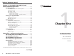
Introduction About this Manual The Extron SW series of switchers includes these models: 1 2 • SW ARxi (SW 2 ARxi, SW 4 ARxi ) • SW AR HVxi (SW 2 AR HVxi, SW 4 AR HVxi, SW 6 AR HVxi ) SW 2 AR MX SW 4 AR • SW AR MX (SW 2 AR MX, SW 4 AR MX, SW 6 AR MX) • SW AR MX HV (SW 4 AR MX HV, SW 6 AR MX HV) • SW 6 Component About the Switchers Figure 3 — SW 4 ARxi xi The SW series switchers provide switching between analog video sources and destination devices using BNC input and output connectors.
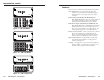
Introduction, cont’d Features 1 2 3 The SW series of switchers includes the following features: 4 SW 4AR MX HV 90-240 VAC, 50/60 Hz FUSE: 250V, 400mA SLO-BLO 1 3 5 6 4 INPUTS 2 INPUTS Figure 9 — SW 4 AR MX HV 1 2 3 4 5 Auto-switch mode — Auto-switch mode allows the switcher to automatically select the highest input number that has a sync signal on the sync input connector.
Introduction, cont’d SW Switchers 2 Chapter Two Installation Front and Rear Panels Installing the Switcher Troubleshooting 1-6 SW Switchers • Introduction
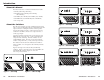
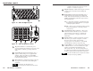
Installation Front and Rear Panels 1 Auto switch active LED (SW ARxi and SW AR HVxi only) — Lights to indicate that auto-switch mode is On. The input mode/selection LEDs on SW AR MX, SW AR MX HV, and SW 6 Component switchers accomplish the same function. 2 Input selection buttons — Allow you to select the input to be displayed. The number of buttons available depends on the model. Front panel features Figure 12 shows an SW 6 AR HVxi front panel, and figure 13 shows an SW 6 AR MX HV front panel.
Installation, cont’d 2 5 1 capability. This allows the inputs to be used as outputs. See “Features” on page 1-8. 6 3 4 Output connectors — BNC female output connectors See page 2-7 for information about cabling the connectors. 5 Mode switch (SW ARxi and SW AR HVxi only) — Toggles between auto-switch mode and manual mode. (The same functionality is provided on SW AR MX, SW AR MX HV, and SW 6 Component via front panel buttons.
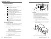
Installation, cont’d Installing the Switcher Installation overview To install a switcher, perform the following general steps: 1 If desired, mount the switcher in a rack (see “Mounting the switcher” below). 2 Turn off power to the input and output devices, and unplug the power cords from them. 3 Attach the input and output devices to the switcher (see “Cabling the switcher” on page 2-7). 4 If you are setting up the switcher in looping mode, see “Looping” on page 2-11.
Installation, cont’d 3. Secure the switcher to the rack panel by reinstalling the four corner screws and beveled (dress) washers through the panel. To avoid shifting, ensure that the switcher is placed firmly against the panel. 2. Use BNC connectors to connect the switcher to the output device. 4. Secure the rack panel to the rack with the hardware provided.
Installation, cont’d (Y) cable to the Y input, and connect the chrominance (C) input cable to either the R-Y or the B-Y input. Input cabling for auto-switching This section applies to SW ARxi, SW AR HVxi, SW AR MX, and SW AR MX HV switchers only. It does not apply to the SW 6 Component switcher. For proper auto-switch operation, the switcher control logic must detect horizontal or composite sync pulses on the H/S sync input connector. Video on the sync input connectors is not passed to the output.
Installation, cont’d With the switchers connected as shown on page 2-12, input selection occurs as shown below. Output For SW ARxi and SW AR HVxi switchers, Loop Out is on pin 24 of the 25-pin connector, and Loop In is on pin 12. For SW AR MX and SW AR MX HV switchers, Loop Out is on the Loop Out BNC connector, and Loop In is on the Loop In BNC connector. A • Any input selected by switcher A is seen at the output.
Installation, cont’d (Loop In). Connect switcher B’s contact remote connector pin 24 (Loop Out) to switcher A’s contact remote connector pin 12 (Loop In). To connect the switcher to the KP-10 wired remote keypad, attach the keypad’s cable to the contact/manual remote 25-pin connector on the switcher. For SW AR MX and SW AR MX HV switchers: Connect switcher C’s Loop Out connector to switcher B’s Loop In connector. Connect switcher B’s Loop Out connector to switcher A’s Loop In connector.
Installation, cont’d 5. Power the switcher on. To operate the IR-101, press the key for the desired input while aiming the hand-held unit at the IR detector. The approximate operating range is 30 feet. To change the selected input to 1 on an SW AR MX, SW AR MX HV, or SW 6 Component switcher, remote connector pin 1 must be shorted to ground for less than 2 seconds. If pin 1 is shorted for 2 seconds or longer, the mode is displayed by a blinking LED, and the selected input does not change.
Installation, cont’d Troubleshooting SW Switchers The sections below shows some common operating problems and their solutions. All models Problem — Pressing an input selection button does not change the input. Solution — Verify the operating mode. The input selection buttons do not change the input if the switcher is in auto-switch mode or (for SW AR MX, SW AR MX HV, and SW 6 Component switchers only) auto-sequence mode.
xi Operation SW ARxi xi and SW AR HVxi This chapter applies to SW ARxi and SW AR HVxi switchers only. For SW AR MX, SW AR MX HV, and SW 6 Component switcher operation information, see chapter 4. Operating Modes SW ARxi and SW AR HVxi switchers operate in two modes: front panel mode and auto-switch mode. The Mode switch on the switcher’s rear panel toggles between modes.
xi and SW AR HVxi xi Operation, cont’d SW ARxi Following are two examples of Switch DOS commands. RS-232 2-4-6-8 adapter software DOS and Windows® -compatible software, for controlling SW ARxi and SW AR HVxi switchers through the RS-232 2-4-6-8 adapter, is provided on a 3.5-inch diskette. Both versions enable the switcher input number to be selected from the host computer/device. The DOS version of software for SW ARxi and SW AR HVxi switcher input selection is a program called "Switch".
xi and SW AR HVxi xi Operation, cont’d SW ARxi Using the software To run the RS-232 2-4-6-8 Control Program, do the following: SW Switchers 1. Double-click on the RS-232 2-4-6-8 Control Pgm icon in the Extron Electronics group or folder. The RS-232 2-4-6-8 Control Program appears. 2. From the Com menu, click on the comm port that is connected to the RS-232 2-4-6-8 adapter port. 3. From the Size menu, click on the switcher type.
SW AR MX, SW AR MX HV, and SW 6 Component Operation This chapter applies to SW AR MX, SW AR MX HV, and SW 6 Component switchers only. For SW ARxi and SW AR HVxi operation information, see chapter 3. SW AR MX, SW AR MX HV, and SW 6 Component switchers operate in three modes: front panel mode, autoswitch mode, and auto-sequence mode. To determine the current mode, press and hold front panel button #1 until LED #2, 3, or 4 begins blinking. The blinking LED identifies the mode, as shown below.
SW AR MX, SW AR MX HV, and SW 6 Component Operation, cont’d Auto-sequence mode Sequence rate decoding — alternate method In auto-sequence mode, the switcher scans all inputs at a rate defined by the sequence rate. The sequence rate is set through the front panel buttons for time periods ranging from 4 to 60 seconds. In this mode, an input remains selected for the period of time specified by the sequence rate, then the next input in sequence is selected.
SW AR MX, SW AR MX HV, and SW 6 Component Operation, cont’d Do not touch any electronic components inside the switcher. Doing so could damage the switcher. See the System 4 Series Switcher manual for configuration information regarding the connection of an SW AR MX type switcher as a slave to a System 4 switcher. Lift cover straight up.
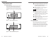
SW AR MX, SW AR MX HV, and SW 6 Component Operation, cont’d Command/response table Definitions and abbreviations: V = Video input F = Function (mode ) M = Maximum inputs (2, 4, or 6) 90-240 VAC, 50/60 Hz FUSE: 250V, 400mA SLO-BLO 1 3 5 6 INPUTS 4 2 INPUTS SW 6 AR MX HV 5 ! = Delimiter character = Indicates end of input selection.
SW AR MX, SW AR MX HV, and SW 6 Component Operation, cont’d instructions that appear on the screen. The program occupies approximately 1 MB (megabyte) of hard drive space. By default, the Windows installation creates a C:\UNIVSW directory, and it places two icons (Universal Switcher Control Pgm and Universal Switcher Help) into a group or folder named “Extron Electronics”.
SW AR MX, SW AR MX HV, and SW 6 Component Operation, cont’d Battery backup If a loss of AC line voltage occurs, the current operating mode and the selected input are saved. When AC line voltage returns, the saved mode and input are restored and, the switcher resumes operation. The battery backup feature normally preserves the information for up to one hour. However, this time may be less if the switcher has been powered on for less than three minutes prior to the loss of AC line voltage.
Reference cont’d ReferenceInformation, Information SW2 ARxi,SW4 ARxi, SW2/4/6 AR HVxi Specifications Video Gain ................................................... Unity Bandwidth ........................................ 350 MHz (-3dB) Switching speed .............................. 5 mS (max.) Video input Number/signal type SW2/4 ARxi ........................ 2 or 4 RGBS, RGsB, RsGsBs, component video, S-video, NTSC/PAL/SECAM composite video SW2/4/6 AR HVxi ............
Reference Information, cont’d SW AR MX Specifications Video Gain ............................................... Bandwidth .................................... Crosstalk ....................................... Switching speed ........................... Unity 600 MHz (-3dB), fully loaded -70dB @ 10 MHz 5 mS (max.) Video input Number/signal type ................... 2, 4, or 6 analog VGA-UXGA RGBS, RGsB, RsGsBs, component video, S-video or NTSC/PAL/SECAM composite video Connectors ..........................
Reference Information, cont’d SW 4/6 AR MX HV Specifications Video Gain ............................................... Bandwidth .................................... Crosstalk ....................................... Switching speed ........................... Unity 600 MHz (-3dB), fully loaded -70dB @ 10 MHz 5 mS (max.) Video input Number/signal type ...................
Reference Information, cont’d MTBF ............................................. 30,000 hours Warranty ....................................... 3 years parts and labor Control/remote — switcher Specifications are subject to change without notice. (7.31-010302-D1) SW 6 Component Specifications Video Gain ............................................... Unity Bandwidth .................................... 180 MHz (-3dB), fully loaded Crosstalk .......................................
Reference Information, cont’d Cable part numbers Part Numbers Extron Part BNC-4 HR cable xi part numbers SW ARxi xi and SW AR HVxi Extron Part Part # SW 2 ARxi ......................................................................... 60-262-01 SW 2 AR HVxi ......................................................... 60-263-01 SW 4 ARxi ................................................................ 60-264-01 SW 4 AR HVxi ..................................................................
Reference Information, cont’d A-12 SW Switchers • Reference Information