
User`s manual

SW AR
xixi
xixi
xi and SW AR HV
xixi
xixi
xi • OperationSW AR
xixi
xixi
xi and SW AR HV
xixi
xixi
xi • Operation
SW AR
xixi
xixi
xi and SW AR HV
xixi
xixi
xi Operation
switchers support the Extron RS-232 2-4-6-8 Contact
Closure Adapter. The adapter, connected to the switcher's
contact remote connector, allows an RS-232 host computer/
device to duplicate SW ARxi front panel operations. (See
page 2-16 for contact remote connector pin assignment
information.)
Communication between the adapter and the host is in only
one direction. The adapter receives two decimal codes and
converts them to a momentary switch contact closure that
parallels the switcher's front panel switch through the
25-pin contact remote connector. There is no response from
the adapter to the host.
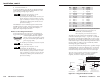
The first decimal code is the input selection code, and the
second decimal code must be code 255, which is the clear
code. The clear code is required to clear the RS-232 2-4-6-8
adapter buffer. The input selection codes representing each
switcher input number are listed in the second table on
page 3-4.
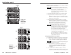
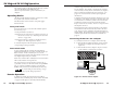
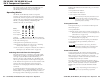
Connecting the RS-232 2-4-6-8 adapter
To connect the RS-232 2-4-6-8 adapter, do the following:
1. Connect the RS-232 cable from the PC serial port to the
RS-232 2-4-6-8 adapter’s RS-232 input connector
(figure 26).
2. Connect the RS-232 2-4-6-8 adapter’s 25-pin connector
to the switcher's contact remote connector.
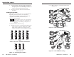
Figure 26 — RS-232 2-4-6-8 adapter
This chapter applies to SW ARxi and SW AR HVxi switchers
only. For SW AR MX, SW AR MX HV, and
SW 6 Component switcher operation information, see
chapter 4.
Operating Modes
SW ARxi and SW AR HVxi switchers operate in two modes:
front panel mode and auto-switch mode.
The Mode switch on the switcher’s rear panel toggles
between modes.
Front panel mode
In front panel mode, you can select the switcher input in
the following ways:
• Front panel buttons (see below)
• Optional remote control device (contact closure type) via
the remote connector (see “Attaching remote control
devices” on page 2-14)
• Optional host device/computer via the RS-232 2-4-6-8
adapter (see “Remote operation” below)
To select the input from the front panel, press the button
corresponding to the input number.
Auto-switch mode
In auto-switch mode, the switcher selects the highest
numbered input that has sync pulses available on the sync
BNC connector. In the event that sync is lost on the
selected input, the switcher will automatically switch to the
next highest input with sync available.
When auto-switch mode is enabled, the Auto Switch Active
LED on the switcher’s front panel is lit.
The auto-switch sync sensing circuitry monitors the "S"
(sync) BNC connector for all video formats except RGBHV.
The "V" (vertical sync) BNC connector is monitored if
RGBHV video format is used (SW AR HVxi models only).
See “Input cabling for auto-switching” on page
2-10 for special cabling requirements.
Remote Operation
In addition to the KP-10 wired remote keypad, IR-10
infrared remote, and third-party remote controls described
on pages 2-13 through 2-16, SW ARxi and SW AR HVxi
3-3
Computer Control
DB9 Pin Locations
Female
51
96
SW 6 AR HVxi
RS-232 2-4-6-8
Controller
RS-232
INPUT
3-2